Hyundai Genesis (DH): Rear Axle Assembly / Rear Hub - Carrier Repair procedures
Hyundai Genesis (DH) 2013-2016 Service Manual / Driveshaft and axle / Rear Axle Assembly / Rear Hub - Carrier Repair procedures
| Replacement |
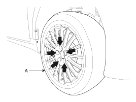
| 1. |
Loosen the wheel nuts slightly. Raise the vehicle, and make sure it is securely supported. |
| 2. |
Remove the rear wheel and tire from the rear hub.
|

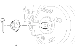
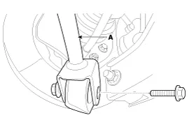
| 3. |
Remove the split pin, then remove castle nut (A) and washer from the front hub.
|
| 4. |
Remove the brake caliper assembly.
(Refer to Brake System - "Rear Disc Brake") |
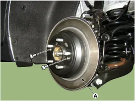
| 5. |
Remove the rear brake disc (A).
|
| 6. |
Remove the parking brake cable.
(Refer to Brake System - "Parking Brake System") |
| 7. |
Remove the parking brake shoe
(Refer to Brake System - "Parking Brake System") |
| 8. |
Loosen the wheel speed sensor mounting bolt and then remove the sensor (A).
|

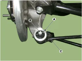
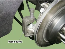
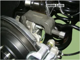
| 9. |
Loosen the split pin (A) & nut (B) and remove the assist arm (C) using a SST (09568-2J100).
|
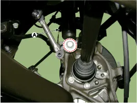
| 10. |
loosen the bolt & nut and then remove the trailing arm (A).
|
| 11. |
Remove the shock absorber (A) from the rear axle by loosening the shock absorber mounting bolt.
|
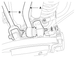
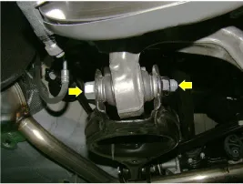
| 12. |
Remove the rear upper arm front(B) and rear upper arm rear(A).
(1) Loosen the bolt & nut and remove the rear upper arm front (B).
(2) Remove the split pin and nut and then remove the rear upper arm rear (A).
|
| 13. |
Remove lower arm from rear axle carrier.
|
| 14. |
Remove hub assembly mounting bolt (B), (C) and then separate the rear hub bearing from the rear carrier.
|

| 15. |
Install in the reverse order of removal.
|
| 16. |
Check the front alignment.
(Refer to Suspension System - "Rear Alignment") |
| Inspection |
| 1. |
Check the hub for cracks and the splines for wear. |
| 2. |
Check the brake disc for scoring and damage. |
| 3. |
Check the knuckle for cracks. |
| 4. |
Check the bearing for cracks or damage. |
Components 1. Rear carrier2. Dust shield assembly3. Rear hub bearing4. Rear brake disc
Other information:
Hyundai Genesis (DH) 2013-2016 Service Manual: Compressor Repair procedures
Removal 1. If the compressor is marginally operable, run the engine at idle speed, and let the air conditioning work for a few minutes, then shut the engine off. 2. Disconnect the negative (-) battery terminal. 3. Remove the engine room cover.
Hyundai Genesis (DH) 2013-2016 Service Manual: Auto Defogging Sensor Repair procedures
R
Categories
- Manuals Home
- Hyundai Genesis Owners Manual
- Hyundai Genesis Service Manual
- Active Air Flap(AAF) Repair procedures
- Steering System
- Emission Control System
- New on site
- Most important about car

Copyright © 2026 www.hgenesisdh.com - 0.0503