Hyundai Genesis (DH): Seat Belt Pretensioner / Pre-activeSeat Belt Unit (PSB) Repair procedures
Hyundai Genesis (DH) 2013-2016 Service Manual / Restraint / Seat Belt Pretensioner / Pre-activeSeat Belt Unit (PSB) Repair procedures
| Removal |
| 1. |
Disconnect the battery negative cable, and wait for at least three minutes before beginning work. |
| 2. |
Remove the crash pad lower panel.
(Refer to Body - "Crash Pad Lower Panel") |
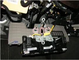
| 3. |
Remove the mounting nuts (A).
|

| 4. |
Disconnect the knee airbag connector (B).
|
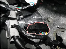
| 5. |
Disconnect the psb ecu connector (A).
|
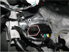
| 6. |
Remove the mounting psb ecu nut (B).
|

| Installation |
| 1. |
Disconnect the battery negative cable and wait for at least three minutes before beginning work. |
| 2. |
Install the psb ecu |
| 3. |
Install the psb ecu connector
|
| 4. |
Install the knee airbag . |
| 5. |
Install the crash pad lower panel.
(Refer to Body - "Crash Pad Lower Panel") |
| 6. |
Reconnect the battery negative cable. |
| PSB Variant Coding |
When replacing a PSB of the driver
Circuit Diagram
Other information:
Hyundai Genesis (DH) 2013-2016 Service Manual: Parking Assist Sensor Repair procedures
Removal 1. Disconnect the negative (-) battery terminal. 2. Remove the front/rear bumper cover. (Refer to Body - "Front Bumper Cover") (Refer to Body - "Rear Bumper Cover") 3. Disconnect the connector (B) from the parking assist sensor (A).
Hyundai Genesis (DH) 2013-2016 Service Manual: Heater Unit Repair procedures
R
Categories
- Manuals Home
- Hyundai Genesis Owners Manual
- Hyundai Genesis Service Manual
- Description and Operation
- Repair procedures
- Emission Control System
- New on site
- Most important about car

Copyright © 2026 www.hgenesisdh.com - 0.0271