Hyundai Genesis: Power Windows / Power Window Switch Repair procedures
Diagnosis With GDS
| 1. |
In the body electrical system, failure can be quickly diagnosed by using the vehicle diagnostic system (GDS).
| (1) |
Self diagnosis : Checking failure and code number (DTC) |
| (2) |
Current data : Checking the system input/output data state |
| (3) |
Actuation test : Checking the system operation condition |
| (4) |
Additional function : Controlling other features including system option setting and zero point adjustment |
|
| 2. |
Select the 'Car model' and the system to be checked in order to check the vehicle with the tester. |
| 3. |
Select the 'Driver seat or Assistant seat door module (DDM/ADM)' to check the driver seat or assistant door module (DDM/ADM). |
| 4. |
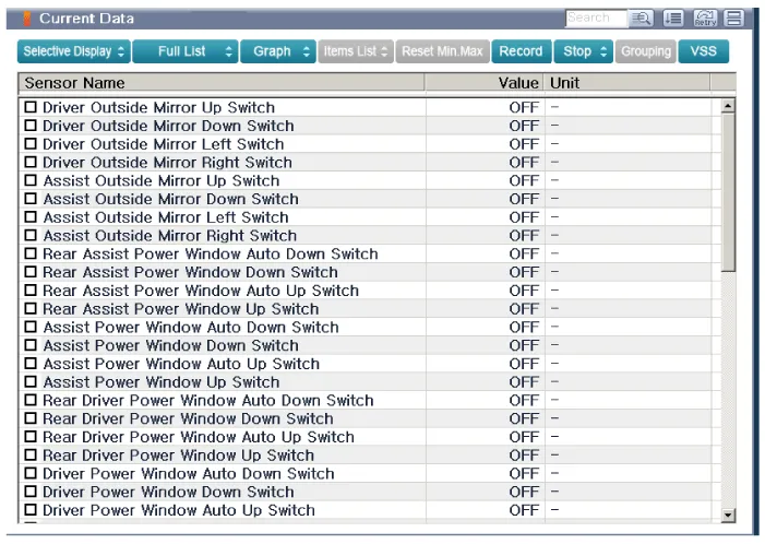
Select the "Current Data" menu to search the current state of the input/output data.
The input/output data for the sensors corresponding to the driver seat or assistant door module(DDM/ADM) can be checked. 
|
| 5. |
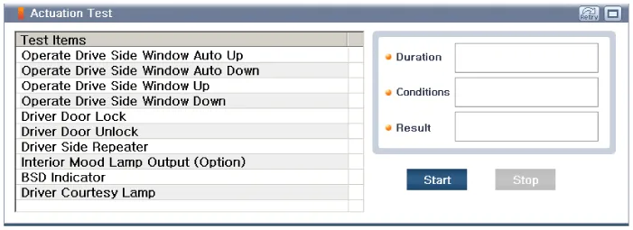
If you will check the power door lock operation forcefully, select "Actuation test". 
|
Driver Power Window Switch
| • |
Wrap the protective tape on the tool to disassemble with the screwdriver or remover. |
| • |
Use caution in keeping and handling during disassembling/assembling because it is easily contaminated with lubricant and oil. |
| • |
Use caution for the crash pad garnish and door trim upper
garnish made of timber (Real wood) because they can be scratched or
picked. |
| • |
Be careful not to scratch the door trim and other parts. |
|
| 1. |
Disconnect the negative(-) battery terminal. |
| 2. |
Remove the front door trim panel. |
| 3. |
Disconnect the DDM(Driver Door Module) connector (A) from the wiring harness. 
|
| 4. |
If the trim interferes with the removal process, remove the trim (A) after loosening the mounting screws. 
|
| 5. |
Remove the DDM(Driver Door Module) (A) after loosening the mounting screws. 

|
Assist Power Window Switch
| • |
Wrap the protective tape on the tool to disassemble with the screwdriver or remover. |
| • |
Use caution in keeping and handling during disassembling/assembling because it is easily contaminated with lubricant and oil. |
| • |
Use caution for the crash pad garnish and door trim upper
garnish made of timber (Real wood) because they can be scratched or
picked. |
| • |
Be careful not to scratch the door trim and other parts. |
|
| 1. |
Disconnect the negative(-) battery terminal. |
| 2. |
Remove the front door trim panel. |
| 3. |
Disconnect the ADM(Assist Door Module) connector (A) from the wiring harness. 
|
| 4. |
Remove the obstacle trim (A) after loosening the mounting screws. 
|
| 5. |
Remove the ADM(Assist Door Module) (A) after loosening the mounting screws. 

|
Rear Power Window Switch
| 1. |
Disconnect the negative (-) battery terminal. |
| 2. |
Remove the rear door trim.
(Refer to Body - "Rear Door Trim") |
| 3. |
Remove the power window switch assembly (A) after loosening the mounting screws. 

|
Driver Power Window Switch
| 1. |
Install the power window switch assembly. |
| 2. |
Install the front door trim after connect the connector. |
Assist Power Window Switch
| 1. |
Install the power window switch assembly. |
| 2. |
Install the front door trim after connect the connector. |
Rear Power Window Switch
| 1. |
Install the power window switch assembly. |
| 2. |
Install the rear door trim after connect the connector. |
Circuit Diagram
Driver Power Window Switch
Assist Power Window Switch
Rear Power Window Switch
...
Other information:
Removal
1.
Turn ignition switch OFF and disconnect the negative (-) battery cable.
2.
Remove the Engine room fuse & relay box (B) after removing the cover (A).
3.
Disconnect the brake tubes (A) from the HECU by unlocking the nuts counterclockwise with a wrench.
Tightening torque : ...
Inspection
1.
Turn the ignition switch OFF.
2.
Disconnect the IATS connector.
3.
Measure resistance between the IATS terminals 3 and 4.
4.
Check that the resistance is within the specification.
Specification: Refer to “Specification”
Removal
1.
Turn the ignition swit ...