Hyundai Genesis (DH): Indicators And Gauges / Instrument Cluster Components and Components Location
Hyundai Genesis (DH) 2013-2016 Service Manual / Body Electrical System / Indicators And Gauges / Instrument Cluster Components and Components Location
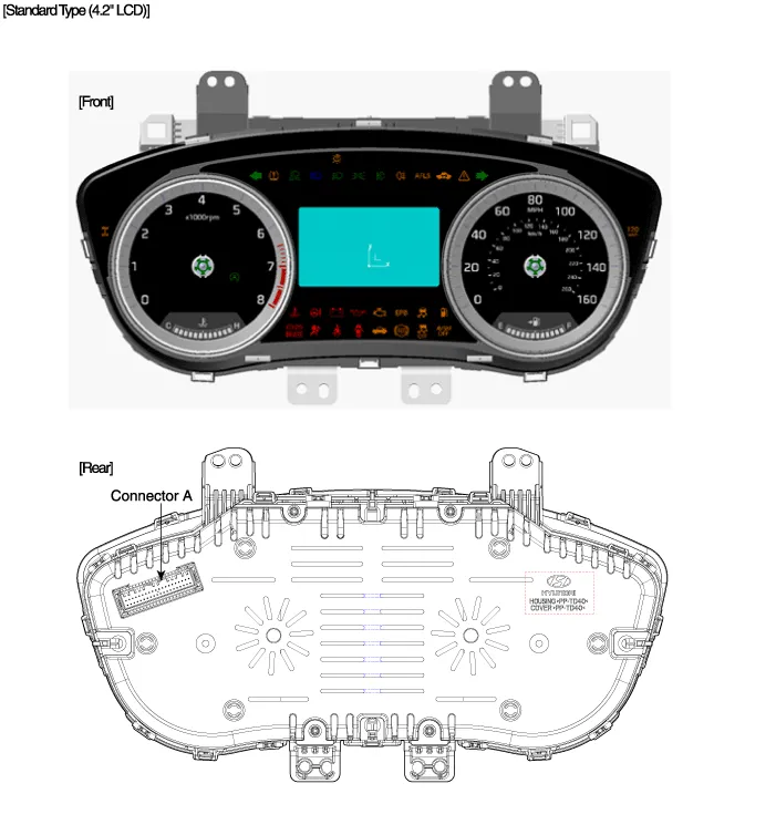
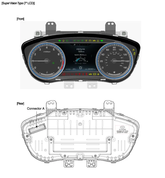
| Components |
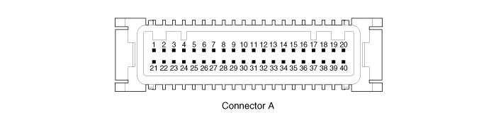
Connector Pin Information
| No. | Description | No. | Description |
| 1 | - | 21 | - |
| 2 | Illumination output | 22 | - |
| 3 | Rheostat down switch | 23 | 4P output |
| 4 | Rheostat up switch | 24 | Immobilizer |
| 5 | AT N output | 25 | AT S output |
| 6 | Oil pressure | 26 | AT R output |
| 7 | Low washer | 27 | AT P output |
| 8 | Charge | 28 | - |
| 9 | AT D output | 29 | - |
| 10 | Illumination + | 30 | MM_CAN High |
| 11 | - | 31 | MM_CAN Low |
| 12 | Active ECO | 32 | C_CAN High |
| 13 | Heated wheel indicator | 33 | C_CAN Low |
| 14 | Fuel | 34 | Trip switch1 |
| 15 | Detent output | 35 | Trip switch2 |
| 16 | Fuel ground | 36 | Trip switch ground |
| 17 | - | 37 | Signal ground |
| 18 | Speaker - | 38 | - |
| 19 | Speaker + | 39 | IGN + |
| 20 | Aig bag + | 40 | Battery + |
Circuit Diagram
Other information:
Hyundai Genesis (DH) 2013-2016 Service Manual: Components and Components Location
C
Hyundai Genesis (DH) 2013-2016 Service Manual: Compressor Repair procedures
Removal 1. If the compressor is marginally operable, run the engine at idle speed, and let the air conditioning work for a few minutes, then shut the engine off. 2. Disconnect the negative (-) battery terminal. 3. Remove the engine room cover.
Categories
- Manuals Home
- Hyundai Genesis Owners Manual
- Hyundai Genesis Service Manual
- Body Electrical System
- Restraint
- Front Door
- New on site
- Most important about car

Copyright © 2026 www.hgenesisdh.com - 0.0211