Hyundai Genesis (DH): Automatic Transmission Control System / Inhibitor Switch Schematic Diagrams
Hyundai Genesis (DH) 2013-2016 Service Manual / Automatic Transmission System (SBC) / Automatic Transmission Control System / Inhibitor Switch Schematic Diagrams
| Circuit Diagram |
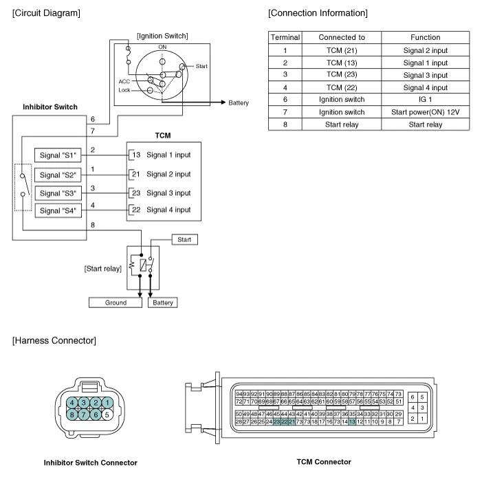
Specifications ? Type: Combination of output signals from 4 terminals Power supply (V)12Output typeCombination of output signals Signal Code Table PIN No.
Inspection
Other information:
Hyundai Genesis (DH) 2013-2016 Service Manual: Auto Head Lamp Leveling Unit Troubleshooting
Inspection with GDS Initialization and diagnosis sequence by using GDS equipment. The following is the summarized A/S procedure. NoProcedure1Park the vehicle on level ground2Tire check3IGN1 ON4Head lamp Low Beam ON5Connection with diagnostic tool6Initial command by diagnostic tool7Clear DTC Code8IGN1 OFF > ON9Re- Connection with diagnostic t
Hyundai Genesis (DH) 2013-2016 Service Manual: Evaporator Temperature Sensor Repair procedures
I
Categories
- Manuals Home
- Hyundai Genesis Owners Manual
- Hyundai Genesis Service Manual
- Transmission Control Module (TCM) Repair procedures
- Active Air Flap(AAF) Repair procedures
- Parking Assist Sensor Repair procedures
- New on site
- Most important about car

Copyright © 2026 www.hgenesisdh.com - 0.0237