Hyundai Genesis (DH): Ignition System / Ignition Coil Repair procedures
Hyundai Genesis (DH) 2013-2016 Service Manual / Engine Electrical System / Ignition System / Ignition Coil Repair procedures
| Removal |
Ignition Coil #1
| 1. |
Turn the ignition switch OFF and disconnect the battery negative (-) cable. |
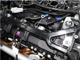
| 2. |
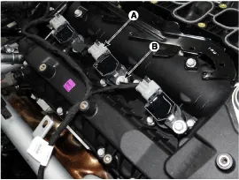
Remove the engine wiring protector (A) after loosening the bolt.
|
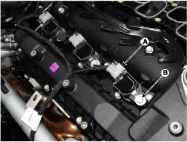
| 3. |
Disconnect the ignition coil connector (A). |
| 4. |
Remove the ignition coil from engine after removing mounting bolt (B).
|
Ignition Coil #2
| 1. |
Turn the ignition switch OFF and disconnect the battery negative (-) cable. |
| 2. |
Remove the surge tank assembly.
(Refer to Engine Mechanical System - "Surge Tank") |
| 3. |
Disconnect the ignition connector (A). |
| 4. |
Remove the ignition coil from engine after removing mounting bolt (B).
|
Ignition Coil #3
| 1. |
Turn the ignition switch OFF and disconnect the battery negative (-) cable. |
| 2. |
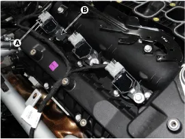
Remove the engine wiring protector (A) after loosening the bolt.
|
| 3. |
Disconnect the ignition coil connector (A). |
| 4. |
Remove the ignition coil from engine after removing mounting bolt (B).
|
Ignition Coil #4
| 1. |
Turn the ignition switch OFF and disconnect the battery negative (-) cable. |
| 2. |
Remove the surge tank assembly.
(Refer to Engine Mechanical System - "Surge Tank") |
| 3. |
Disconnect the ignition coil connector (A). |
| 4. |
Remove the ignition coil from engine after removing mounting bolt (B).
|
Ignition Coil #5
| 1. |
Turn the ignition switch OFF and disconnect the battery negative (-) cable. |
| 2. |
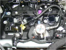
Remove the engine wiring protector (A) after loosening the bolt.
|
| 3. |
Disconnect the ignition coil connector (A). |
| 4. |
Remove the ignition coil from engine after removing mounting bolt (B).
|
Ignition Coil #6
| 1. |
Turn the ignition switch OFF and disconnect the battery negative (-) cable. |
| 2. |
Remove the surge tank assembly.
(Refer to Engine Mechanical System - "Surge Tank") |
| 3. |
Disconnect the ignition coil connector (A). |
| 4. |
Remove the ignition coil from engine after removing mounting bolt (B).
|
| Installation |
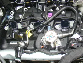
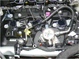
Do not confuse the ignition coil #2 with #4 connections.
Doing so may cause the engine to stall due to incomplete
ignition. And, since unburned fuel flows into the catalyst, this can
overheat and damage the catalyst.
A yellow tag (A) is attached to ignition coil #4. Use this tag for reference when connecting the ignition coils.
|

| 1. |
Install in the reverse order of removal.
|
| Inspection |
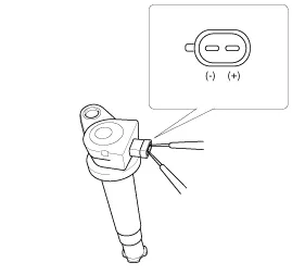
| 1. |
Measure the primary coil resistance between terminals (+) and (-).
Circuit Diagram Description A spark plug is a device for delivering electric current from an ignition system to the combustion chamber of a spark-ignition engine to ignite the compressed fuel/air mixture therein by means of an electric spark, while containing combustion pressure within the engine. Other information:Hyundai Genesis (DH) 2013-2016 Service Manual: Components and Components LocationC Hyundai Genesis (DH) 2013-2016 Service Manual: Heater & A/C Control Unit Components and Components LocationC Categories

Copyright © 2026 www.hgenesisdh.com - 0.0268
|