Hyundai Genesis (DH): Blind Spot Detection system / Blind Spot Detection Unit Repair procedures
Hyundai Genesis (DH) 2013-2016 Service Manual / Body Electrical System / Blind Spot Detection system / Blind Spot Detection Unit Repair procedures
| Removal |
| 1. |
Disconnect the negative (-) battery terminal. |
| 2. |
Remove the rear bumper.
(Refer to Body - "Rear Bumper") |
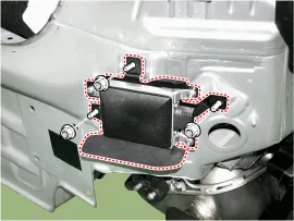
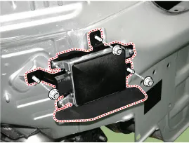
| 3. |
Remove the BSD unit (A) after loosening the mounting nuts.
|

| Installation |
| 1. |
Install the BSD units to the rear panel. |
| 2. |
Install the rear bumper. |
| 3. |
Connect the negative (-) battery terminal.
|
| Inspection |
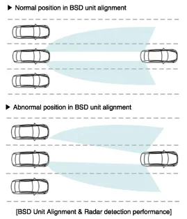
| BSD Unit Alignment |
To correctly sense vehicles on the neighboring lanes using
the radar, the direction of the sensor and the direction of the vehicle
must be aligned.
This is the BSD unit alignment. If this alignment is not
performed as in illustration below, it may cause degradation of
detection performance and false alarms.
In particular, rear bumper accident vehicles and vehicles that replaced BSD unit must carry out this alignment procedure.
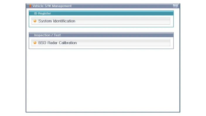
| 1. |
Rear bumper accident vehicles and vehicles that replaced BSD units must perform BSD unit alignment using GDS. |
| 2. |
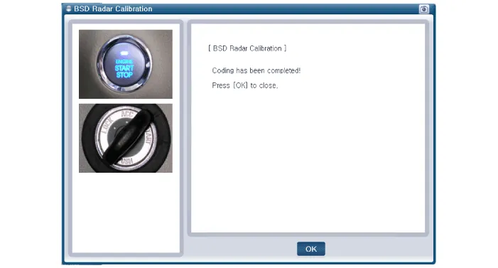
Select "BSD Radar Calibration" procedure in BSD system.
|
| 3. |
Perform the "BSD Radar Calibration" procedure according to the GDS screen message.
|
Circuit Diagram
Circuit Diagram
Categories
- Manuals Home
- Hyundai Genesis Owners Manual
- Hyundai Genesis Service Manual
- Brake System
- Description and Operation
- Emission Control System
- New on site
- Most important about car

Copyright © 2026 www.hgenesisdh.com - 0.0345