
Hyundai Genesis (DH): Engine Control System / Variable Intake Solenoid (VIS) Valve Schematic Diagrams
| Circuit Diagram |
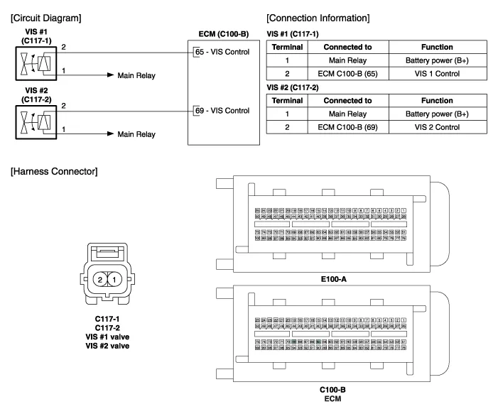
Specification ItemSpecificationCoil Resistance (?)30.0 ~ 35.0 [20
Inspection 1. Turn the ignition switch OFF. 2. Disconnect the VIS valve connector. 3. Measure resistance between the VIS valve terminals 1 and 2.
Other information:
Hyundai Genesis (DH) 2013-2016 Service Manual: Auto Head Lamp Leveling Unit Repair procedures
Inspection 1. Ignition "ON". 2. Turn on the head lamp switch. 3. Check that the aim of the head lamp changes smoothly when the head lamp leveling device switch is turned on. 4. If it does not operate well, check the connector and terminals to make sure that they are connected.
Hyundai Genesis (DH) 2013-2016 Service Manual: Heater Unit Components and Components Location
Component Location Components (1) 1. Shower duct (Left)2. Mode actuator (LH)3. Temperature control actuator (LH)4. Temperature door lever (Left)5. Mode actuator (A)6. Console temperature actuator (A)7. Console mode actuator ON/OFF8. Heater case (Left)9.
Categories
- Manuals Home
- Hyundai Genesis Owners Manual
- Hyundai Genesis Service Manual
- Engine Mechanical System
- Description and Operation
- Body (Interior and Exterior)
- New on site
- Most important about car
