
Hyundai Genesis (DH): Fuel Delivery System / Sub Fuel Sender Repair procedures
Hyundai Genesis (DH) 2013-2016 Service Manual / Engine Control / Fuel System / Fuel Delivery System / Sub Fuel Sender Repair procedures
| Removal |
| 1. |
Release the residual pressure in fuel line.
(Refer to Fuel Delivery System - "Release Residual Pressure in Fuel Line") |
| 2. |
Fold the rear seat cushion. |
| 3. |
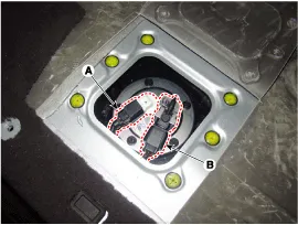
Remove the fuel pump service cover (A) after loosening the screws.
|

| 4. |
Disconnect the sub fuel sender connector (A). |
| 5. |
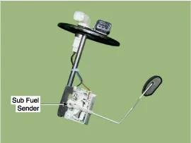
Remove the sub fuel sender (B) from the fuel tank after removing mounting bolts.
|
| Installation |
| 1. |
To install, reverse the removal procedure.
|

| Inspection |
| 1. |
Turn the ignition switch OFF and disconnect the negative (-) battery cable. |
| 2. |
Remove the sub fuel sender. |
| 3. |
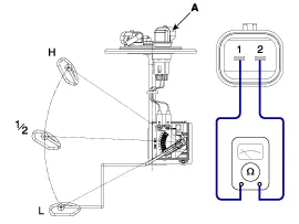
Using an ohmmeter, measure the resistance between terminals 1
and 2 of sender connector (A) at both the highest (H) and lowest (L)
float level.
|
| 4. |
Check that the resistance is within the specification.
|
Removal 1. Release the residual pressure in fuel line. (Refer to Fuel Delivery System - "Release Residual Pressure in Fuel Line") 2. Fold the rear seat cushion.
Removal 1. Release the residual pressure in fuel line. (Refer to Fuel Delivery System -"Release Residual Pressure in Fuel Line")
Other information:
Hyundai Genesis (DH) 2013-2016 Service Manual: Components and Components Location
C
Hyundai Genesis (DH) 2013-2016 Service Manual: In-car Sensor Description and Operation
Description An in-car air temperature sensor is located in the crash pad lower panel. The sensor contains a thermistor which measures the temperature of the cabin. The signal determined by the resistance value which changes in accordance with perceived inside temperature, is delivered to the heater control unit and according to this signa
Categories
- Manuals Home
- Hyundai Genesis Owners Manual
- Hyundai Genesis Service Manual
- Brake System
- Evaporative Emission Control System
- Starter Repair procedures
- New on site
- Most important about car

Copyright В© 2026 www.hgenesisdh.com - 0.0311