Hyundai Genesis (DH): Smart Key System / Smart Key Repair procedures
| Smart Key |
| 1. |
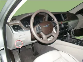
Connect the DLC cable of GDS to the data link connector (16 pins) in driver side crash pad lower panel, turn the power on GDS.
|
| 2. |
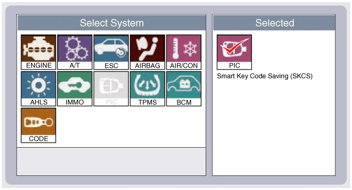
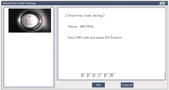
Select the vehicle model and then do "Smart key code saving".
|
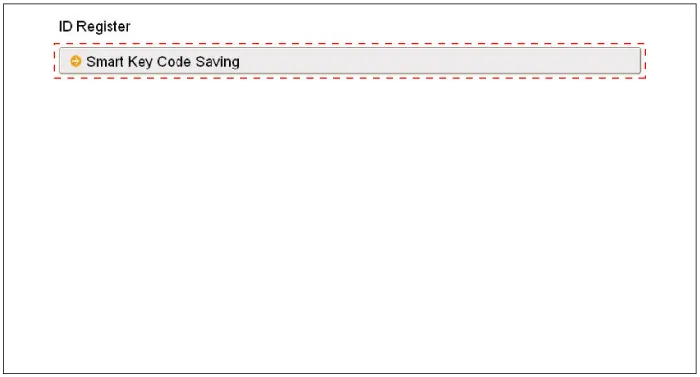
| 3. |
After selecting "Smart key teaching" menu, push "Enter" key, then the screen will be shown as below.
|
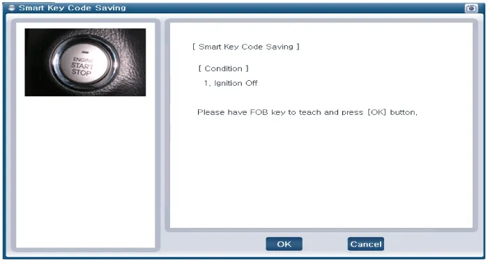
| 4. |
After having the teaching smart key, push "ENTER" key. |
| 5. |
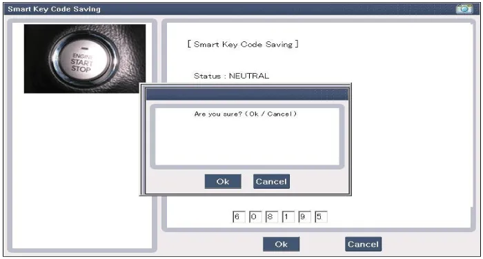
Input the "Pin code" for first key teaching.
|
| 6. |
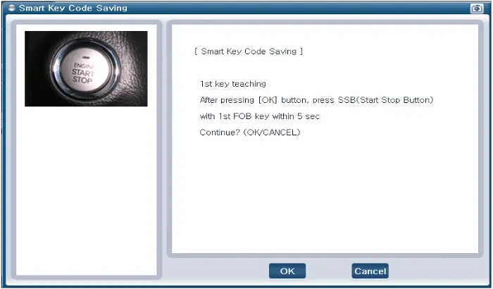
Press the SSB with smart key within 5 sec after pressing "OK".
|
| 7. |
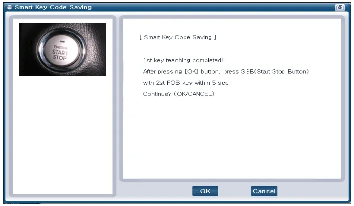
Confirm the message "First key teaching completed".
|
| 8. |
Press the SSB with smart key within 5 sec after pressing "OK".
|
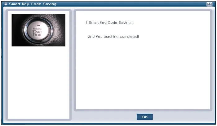
| 9. |
Confirm the message "Second key teaching completed".
|
| 10. |
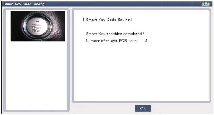
Then the screen will be shown as below when key teaching process is completed.
|
Description Refer to the "Body Network System" for the abbreviation information. The SMART KEY system is a system that allows the user to access and operate a vehicle in a very convenient way.
Components (1) NO.Connector AConnector BConnector C1Immobilizer antenna GNDB+IGN2 input2Bumper antenna GND??3Trunk antenna GNDESCL GRN ESCL enable output4Indoor antenna 2 GND?Assist door button input5Driver's door antenna GNDGNDSSB_switch1 inpuf6Indoor antenna 1 GNDB+POWEREMS CAN7Door antenna assist GND?RPM signal inpuf8SSB_LED OFF outputESCL BAT Wheel speed input9SSB_LED ACC output?Start Feedback signal inpuf10SSB_LED IGN outputGNDBrake switch signal input (Normal Open)11SSB LED POWER?P signal input (AT specification)12??ESCL unlock signal input13Immobilizer antenna power??14Bumper antenna power??15Trunk antenna power??16Indoor antenna 2 power? SSB switch2 inpuf17Driver's door antenna power??18Indoor antenna 1 power??19Assist door antenna power?B CAN LOW20IGN2 relay output?B CAN HIGH21IGN2 relay output?Driver's door switch input22ACC relay output??23SSB LED GND? ESCL CAN24Starter relay output??25???26??ACC 27??IGN2
Other information:
Hyundai Genesis (DH) 2013-2016 Service Manual: Description and Operation
Description Integrated Rain Sensor Integrated rain sensor (A) controls three systems: front wiper, auto-light, and central air conditioner. 1. Wiper Control System When "AUTO" switch signal is received from the multi-function switch on the right, the integrated rain sensor detects the amount of rainfall.
Hyundai Genesis (DH) 2013-2016 Service Manual: Cluster Ionizer Repair procedures
Inspection 1. Press the MODE switch more than 4 times within 2 seconds while pressing the OFF switch. DisplayFail description00Normal51Cluster ion generator fault * For diagnostic procedure, refer to DTC guide. Replacement 1. Disconnect the negative (-) battery terminal.
Categories
- Manuals Home
- Hyundai Genesis Owners Manual
- Hyundai Genesis Service Manual
- Electric Parking Brake (EPB) Repair procedures
- Engine Mechanical System
- Rain Sensor Repair procedures
- New on site
- Most important about car

