
Hyundai Genesis (DH): Smart Key System / Smart Key Unit Components and Components Location
Hyundai Genesis (DH) 2013-2016 Service Manual / Body Electrical System / Smart Key System / Smart Key Unit Components and Components Location
| Components (1) |
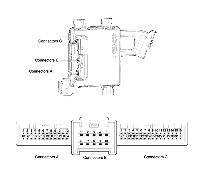
| NO. | Connector A | Connector B | Connector C | |||
| 1 | Immobilizer antenna GND | B+ | IGN2 input | |||
| 2 | Bumper antenna GND | ? | ? | |||
| 3 | Trunk antenna GND | ESCL GRN | ESCL enable output | |||
| 4 | Indoor antenna 2 GND | ? | Assist door button input | |||
| 5 | Driver's door antenna GND | GND | SSB_switch1 inpuf | |||
| 6 | Indoor antenna 1 GND | B+POWER | EMS CAN | |||
| 7 | Door antenna assist GND | ? | RPM signal inpuf | |||
| 8 | SSB_LED OFF output | ESCL BAT | Wheel speed input | |||
| 9 | SSB_LED ACC output | ? | Start Feedback signal inpuf | |||
| 10 | SSB_LED IGN output | GND | Brake switch signal input (Normal Open) | |||
| 11 | SSB LED POWER | ? | P signal input (AT specification) | |||
| 12 | ? | ? | ESCL unlock signal input | |||
| 13 | Immobilizer antenna power | ? | ? | |||
| 14 | Bumper antenna power | ? | ? | |||
| 15 | Trunk antenna power | ? | ? | |||
| 16 | Indoor antenna 2 power | ? | SSB switch2 inpuf | |||
| 17 | Driver's door antenna power | ? | ? | |||
| 18 | Indoor antenna 1 power | ? | ? | |||
| 19 | Assist door antenna power | ? | B CAN LOW | |||
| 20 | IGN2 relay output | ? | B CAN HIGH | |||
| 21 | IGN2 relay output | ? | Driver's door switch input | |||
| 22 | ACC relay output | ? | ? | |||
| 23 | SSB LED GND | ? | ESCL CAN | |||
| 24 | Starter relay output | ? | ? | |||
| 25 | ? | ? | ? | |||
| 26 | ? | ? | ACC | |||
| 27 | ? | ? | IGN2 | |||
Smart Key Smart Key Code Saving 1. Connect the DLC cable of GDS to the data link connector (16 pins) in driver side crash pad lower panel, turn the power on GDS.
Circuit Diagram
Other information:
Hyundai Genesis (DH) 2013-2016 Service Manual: Receiver-Drier Repair procedures
Replacement 1. Remove the condenser. 2. Remove the cap (B) on the bottom of the condenser with the L wrench (A). Tightening torque : 9.81 ~ 14.71 N.m (1.0 ~ 1.5 kgf.m, 7.2 ~ 10.8 lb-ft) 3. Remove the receiver-drier (A) from condenser using a long nose plier.
Hyundai Genesis (DH) 2013-2016 Service Manual: Blower Motor Repair procedures
Inspection 1. Connect the battery voltage and check the blower motor rotation. 2. If the blower motor does not operate well, replace it with a genuine blower motor check for proper operation. 3. Replace the blower motor if it is proved that there is a problem with it.
Categories
- Manuals Home
- Hyundai Genesis Owners Manual
- Hyundai Genesis Service Manual
- Electric Parking Brake (EPB) Repair procedures
- Description and Operation
- Suspension System
- New on site
- Most important about car

Copyright В© 2026 www.hgenesisdh.com - 0.0351