Hyundai Genesis (DH): Fuses And Relays / Relay Box (Passenger Compartment) Repair procedures
| Fuse Inspection |
| 1. |
Check that the fuse holders are loosely held and that the fuses are securely fixed by the holders. |
| 2. |
Check that each fuse circuit has the exact fuse capacity. |
| 3. |
Check the fuses for any damage.
|

| Inspection |
| 1. |
The SJB can be diagnosed by using the GDS. The SJB
communicates with the GDS which then displays inputs and outputs along
with codes. |
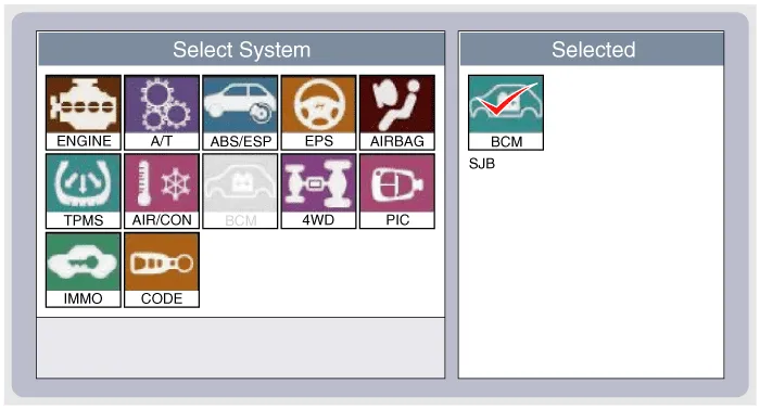
| 2. |
To diagnose the SJB function, select the vehicle model, BCM and SJB.
|
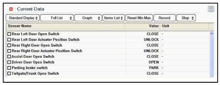
| 3. |
To consult the present input/out value of SJB, "Current DATA". It provides information of SJB input/output conditions.
|
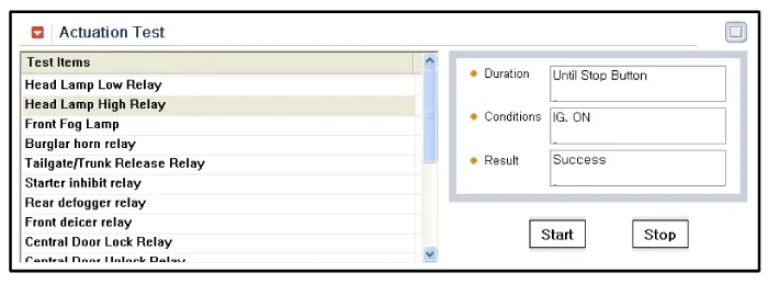
| 4. |
To perform functional test on SJB outputs, select "Actuation Test"
|
| Removal |
| 1. |
Disconnect the negative(-) battery terminal. |
| 2. |
Remove the crash pad lower panel.
(Refer to Body - "Crash Pad Lower Panel") |
| 3. |
Disconnect the connectors from the indoor junction box (smart junction block). |
| 4. |
Remove the smart junction block after loosening the mounting nuts (2EA) and bolt.
|
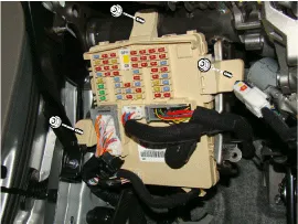
| 5. |
Disconnect the connectors from the back side of the smart junction block. |
| Installation |
| 1. |
Install the smart junction box. |
| 2. |
Install the crash pad lower panel. |
| 3. |
Check that all system operates normally. |
| 4. |
Connect the battery terminal (-). |
Description AppellationDescriptionAAFActive Air FlapACUAirbag Control UnitADMAssist Door ModuleAHDActive Hood SystemAMPAmplifierARSArmrest SwitchASCCAdvanced Smart Cruise ControlAVMAround View MonitorAWDAll Wheel DriveB_CANBody Controller Area NetworkBCMBody Control ModuleBSDBlind Spot DetectionC_CANChassis Controller Area NetworkCCPCenter Control PanelCLUMCluster ModuleDATCDual Automatic Temp ControlDDMDriver Door ModuleDisplayDisplay MonitorDSSDriver Seat SwitchECSElectronic Control SuspentionEMSEngine Management SystemEPBElectronic Parking BrakeEVPEva Vacuum PumpFPCMFuel Pump Control ModuleH/UnitHead UnitHSWSHaptic Steering Warning SystemHUDHead Up DisplayI-BOXTelematics SystemIDBIntegrated Dynamic BrakeLDWSLane Departure Warning SystemM_CANMulti media Controller Area NetworkMDPSMotor Driven Power SteeringMFSMulti-Function SwitchODSOccupant Detection SystemP_CANPowertrain Controller Area NetworkPGSParking Guide SystemPSBPre-Safe Seat BeltPSMPower Seat ModulePTLMPower Trunk Lid ModuleRRCRear Remote ControlSASSteering Angle SensorSCMSteering Column ModuleSJBSmart Junction BoxSLBSeat Lumber BolsterSMKSmart Key UnitSPASSmart Parking Assist SystemSWRCSteering Wheel Remote ControllerTCUTransmission Control UnitTPMSTire Pressure Monitoring SystemVDCVehicle Dynamic Control IGPM (Central Gateway and smart junction block) IGPM (Integrated Gateway Power Control Module) is an integrated model of smart junction block and central gateway.
Other information:
Hyundai Genesis (DH) 2013-2016 Service Manual: Head Up Display Unit Repair procedures
Removal 1. Disconnect the negative (-) battery terminal. 2. Remove the head up display bezel (A). 3. Remove the instrument cluster. (Refer to Indicators And Guages - "Instrument Cluster") 4. Remove the head up display unit bracket (A) after loosening the mounting nuts.
Hyundai Genesis (DH) 2013-2016 Service Manual: Blower Motor Repair procedures
Inspection 1. Connect the battery voltage and check the blower motor rotation. 2. If the blower motor does not operate well, replace it with a genuine blower motor check for proper operation. 3. Replace the blower motor if it is proved that there is a problem with it.
Categories
- Manuals Home
- Hyundai Genesis Owners Manual
- Hyundai Genesis Service Manual
- Engine Mechanical System
- Active Air Flap(AAF) Repair procedures
- Engine Electrical System
- New on site
- Most important about car
