
Hyundai Genesis (DH): Seat Belt Pretensioner / Pre-activeSeat Belt Unit (PSB) Repair procedures
Hyundai Genesis (DH) 2013-2016 Service Manual / Restraint / Seat Belt Pretensioner / Pre-activeSeat Belt Unit (PSB) Repair procedures
| Removal |
| 1. |
Disconnect the battery negative cable, and wait for at least three minutes before beginning work. |
| 2. |
Remove the crash pad lower panel.
(Refer to Body - "Crash Pad Lower Panel") |
| 3. |
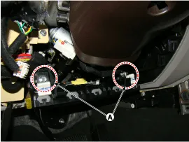
Remove the mounting nuts (A).
|
| 4. |
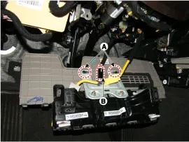
Disconnect the knee airbag connector (B).
|
| 5. |
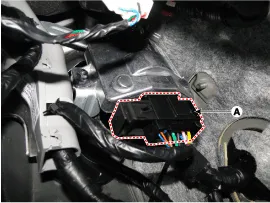
Disconnect the psb ecu connector (A).
|
| 6. |
Remove the mounting psb ecu nut (B).
|

| Installation |
| 1. |
Disconnect the battery negative cable and wait for at least three minutes before beginning work. |
| 2. |
Install the psb ecu |
| 3. |
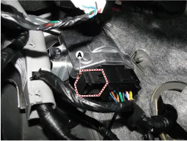
Install the psb ecu connector
|
| 4. |
Install the knee airbag . |
| 5. |
Install the crash pad lower panel.
(Refer to Body - "Crash Pad Lower Panel") |
| 6. |
Reconnect the battery negative cable. |
| PSB Variant Coding |
When replacing a PSB of the driver
Circuit Diagram
Other information:
Hyundai Genesis (DH) 2013-2016 Service Manual: Blind Spot Detection Switch Repair procedures
Removal 1. Disconnect the negative (-) battery terminal. 2. Remove the crash pad lower panel. (Refer to Body - "Crash Pad") 3. Remove the blind spot detection (BSD) switch (A) after disengaging the mounting clip. Installation 1. Install the crash pad side switch assembly after connecting the connector.
Hyundai Genesis (DH) 2013-2016 Service Manual: Power Mosfet Repair procedures
Inspection 1. Turn the ignition switch ON. 2. Manually operate the control switch and control the voltage of the blower motor. 3. Select the control switch to raise the voltage until high speed. Specification Fan Speed (Manual)Motor Voltage (V)13.
Categories
- Manuals Home
- Hyundai Genesis Owners Manual
- Hyundai Genesis Service Manual
- Restraint
- Parking Assist Sensor Repair procedures
- Suspension System
- New on site
- Most important about car

Copyright В© 2026 www.hgenesisdh.com - 0.035