Hyundai Genesis (DH): Power Door Mirrors / Power Door Mirror Actuator Repair procedures
Hyundai Genesis (DH) 2013-2016 Service Manual / Body Electrical System / Power Door Mirrors / Power Door Mirror Actuator Repair procedures
| Inspection |
| 1. |
Disconnect the negative (-) battery terminal. |
| 2. |
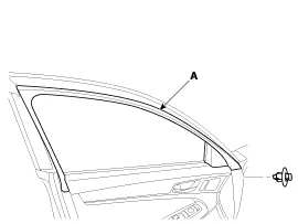
Disconnect the connector (B) after removing the front door frame inner cover (A).
|
| 3. |
Disconnect the power door mirror connector (A) from the harness.
|
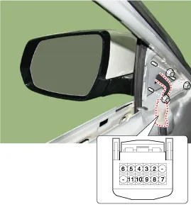
| 4. |
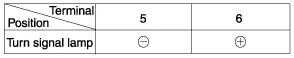
Apply battery voltage to each terminal as shown in the table and verify that the mirror operates properly.
[Turn Signal Lamp]
|
Diagnosis With GDS
| 1. |
In the body electrical system, failure can be quickly diagnosed by using the vehicle diagnostic system (GDS).
|
| 2. |
Select the 'Car model' and the system to be checked in order to check the vehicle with the tester. |
| 3. |
Select the 'Driver seat or Assistant seat door module (DDM/ADM)' to check the driver seat or assistant door module (DDM/ADM). |
| 4. |
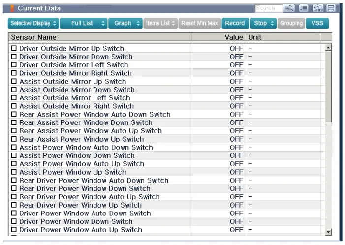
Select the "Current Data" menu to search the current state of the input/output data.
The input/output data for the sensors corresponding to the driver seat or assistant door module(DDM/ADM) can be checked.
|
| 5. |
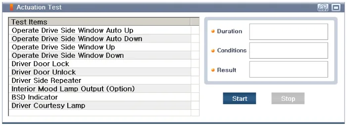
If you will check the power door lock operation forcefully, select "Actuation test".
|
Components 1. AVM Camera2. Ambient temperature sensor3. Puddle lamp
Categories
- Manuals Home
- Hyundai Genesis Owners Manual
- Hyundai Genesis Service Manual
- Heating, Ventilation and Air Conditioning
- Active Air Flap(AAF) Repair procedures
- Steering System
- New on site
- Most important about car

Copyright © 2026 www.hgenesisdh.com - 0.0331