Hyundai Genesis (DH): Engine Control System / Oil Pressure Sensor (OPS) Schematic Diagrams
Hyundai Genesis (DH) 2013-2016 Service Manual / Engine Control / Fuel System / Engine Control System / Oil Pressure Sensor (OPS) Schematic Diagrams
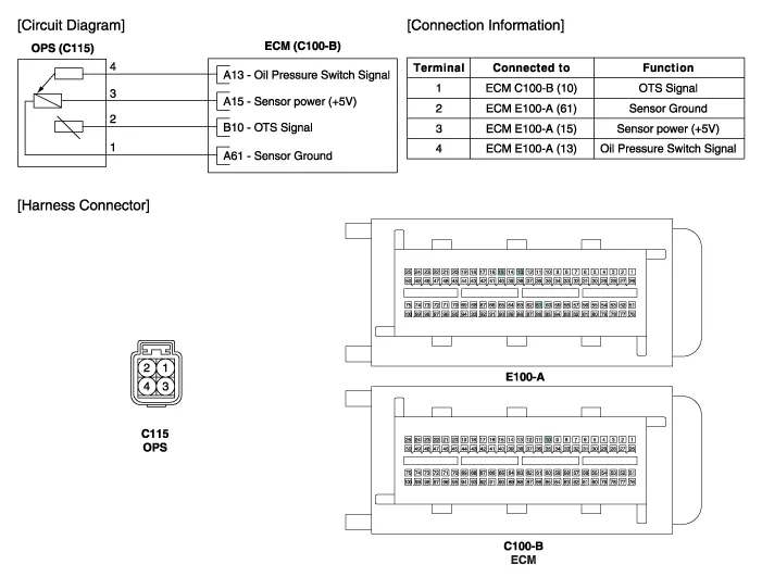
| Circuit Diagram |
Specifications TerminalResistance (k?)2 - 42.76 ~ 4.132 - 31.89 ~ 2.843 - 41.71 ~ 2.84
Inspection 1. Turn the ignition switch OFF. 2. Disconnect the OPS connector. 3. Remove the OPS (Refer to "Removal"). 4. After immersing the thermistor of the sensor into engine coolant, measure resistance between the OPS terminals 1 and 2.
Categories
- Manuals Home
- Hyundai Genesis Owners Manual
- Hyundai Genesis Service Manual
- Emission Control System
- Starter Repair procedures
- Front Door
- New on site
- Most important about car

Copyright © 2026 www.hgenesisdh.com - 0.0239