
Hyundai Genesis (DH): Brake System / Master Cylinder Repair procedures
Hyundai Genesis (DH) 2013-2016 Service Manual / Brake System / Brake System / Master Cylinder Repair procedures
| Removal |
| 1. |
Turn ignition switch OFF and disconnect the negative (-) battery cable. |
| 2. |
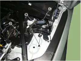
Disconnect the ECM connector (A) and TCM connector (B). IDB (C) and then remove the noise barrier (D).
|
| 3. |
Remove the Cowl Top Cover.
(Refer to Body - "Cowl Top Cover") |
| 4. |
Remove the ECM, TCM & IDB. |
| 5. |
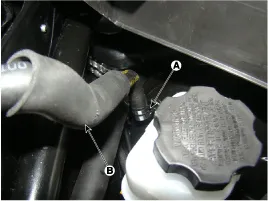
Remove the clamp (A) and brake vacuum hose (B).
|
| 6. |
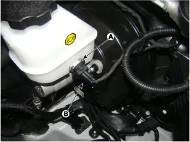
Remove the clip (A) and then disconnect brake fluid level switch connector (B).
|
| 7. |
Remove the brake fluid from the master cylinder reservoir with a syringe.
|

| 8. |
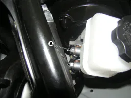
Loosen the hose connecting bolt (A) and disconnect the brake tube.
|
| 9. |
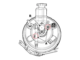
Remove the master cylinder (B) from the brake booster after loosening the mounting nuts (A).
|
| Installation |
| 1. |
To install, reverse the removal procedure. |
| 2. |
After installation, bleed the brake system.
(Refer to Brake System - "Brake System Bleeding") |
Components 1. Reservoir cap2. Reservoir3. Grommet4. Master cylinder
Other information:
Hyundai Genesis (DH) 2013-2016 Service Manual: Repair procedures
Diagnosis With GDS 1. BSD system defects can be quickly diagnosed with the GDS. GDS operates actuator quickly to monitor, input/output value and self diagnosis. 2. Connect the cable of GDS to the data link connector in driver side crash pad lower panel, and turn on the GDS.
Hyundai Genesis (DH) 2013-2016 Service Manual: CO2 Sensor Description and Operation
Description This system maintains the density of carbon dioxide constantly in vehicle interior by measuring the amount of carbon dioxide to increase the comfortableness and the fuel consumption rate when air conditioning system is operating.
Categories
- Manuals Home
- Hyundai Genesis Owners Manual
- Hyundai Genesis Service Manual
- Engine Electrical System
- Body (Interior and Exterior)
- Electric Parking Brake (EPB) Repair procedures
- New on site
- Most important about car

Copyright В© 2026 www.hgenesisdh.com - 0.0253