
Hyundai Genesis (DH): Engine Control System / Knock Sensor (KS) Schematic Diagrams
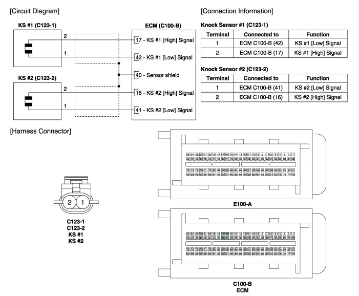
| Circuit Diagram |
Specification ItemSpecificationCapacitance (pF)950 ~ 1,350Resistance (M?)4.87
Removal [Knock Sensor #1 (Bank 1)] 1. Turn the ignition switch OFF and disconnect the battery negative (-) cable. 2. Disconnect the knock sensor connector (A).
Other information:
Hyundai Genesis (DH) 2013-2016 Service Manual: Head Up Display Unit Repair procedures
Removal 1. Disconnect the negative (-) battery terminal. 2. Remove the head up display bezel (A). 3. Remove the instrument cluster. (Refer to Indicators And Guages - "Instrument Cluster") 4. Remove the head up display unit bracket (A) after loosening the mounting nuts.
Hyundai Genesis (DH) 2013-2016 Service Manual: Cluster Ionizer Repair procedures
Inspection 1. Press the MODE switch more than 4 times within 2 seconds while pressing the OFF switch. DisplayFail description00Normal51Cluster ion generator fault * For diagnostic procedure, refer to DTC guide. Replacement 1. Disconnect the negative (-) battery terminal.
Categories
- Manuals Home
- Hyundai Genesis Owners Manual
- Hyundai Genesis Service Manual
- Suspension System
- 4 Wheel Drive (AWD) System
- Evaporative Emission Control System
- New on site
- Most important about car
