Hyundai Genesis (DH): Engine Control System / Knock Sensor (KS) Repair procedures
Hyundai Genesis (DH) 2013-2016 Service Manual / Engine Control / Fuel System / Engine Control System / Knock Sensor (KS) Repair procedures
| Removal |
| [Knock Sensor #1 (Bank 1)] |
| 1. |
Turn the ignition switch OFF and disconnect the battery negative (-) cable. |
| 2. |
Disconnect the knock sensor connector (A).
|
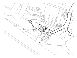
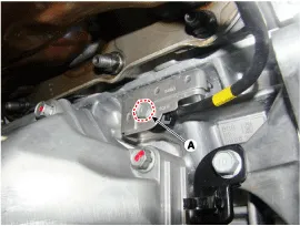
| 3. |
Remove the installation bolt (A), and then remove the sensor from the cylinder block.
|
| [Knock Sensor #2 (Bank 2)] |
| 1. |
Turn the ignition switch OFF and disconnect the battery negative (-) cable. |
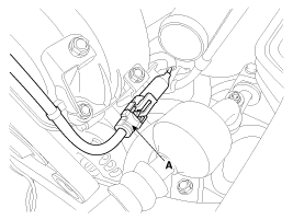
| 2. |
Disconnect the knock sensor connector (A).
|
| 3. |
Drain the engine coolant.
(Refer to Engine Mechanical System - |
Circuit Diagram
Description Heated Oxygen Sensor (HO2S) consists of zirconium and alumina and is installed on upstream and downstream of the Manifold Catalyst Converter (MCC).
Other information:
Hyundai Genesis (DH) 2013-2016 Service Manual: Components and Components Location
C
Hyundai Genesis (DH) 2013-2016 Service Manual: General Safety Information and Caution
Instructions When Handling Refrigerant 1. R-134a liquid refrigerant is highly volatile. A drop on the skin of your hand could result in localized frostbite. When handling the refrigerant, be sure to wear gloves. 2. It is standard practice to wear goggles or glasses to protect your eyes, and gloves to protect your hands.
Categories
- Manuals Home
- Hyundai Genesis Owners Manual
- Hyundai Genesis Service Manual
- Heating, Ventilation and Air Conditioning
- Steering System
- Brake System
- New on site
- Most important about car

Copyright © 2026 www.hgenesisdh.com - 0.0285