Hyundai Genesis (DH): Fuel Delivery System / Fuel Tank Repair procedures
Hyundai Genesis (DH) 2013-2016 Service Manual / Engine Control / Fuel System / Fuel Delivery System / Fuel Tank Repair procedures
| Removal |
| 1. |
Release the residual pressure in fuel line.
(Refer to Fuel Delivery System - "Release Residual Pressure in Fuel Line") |
| 2. |
Turn the ignition switch OFF and disconnect the negative (-) battery cable. |
| 3. |
Fold the rear seat cushion. |
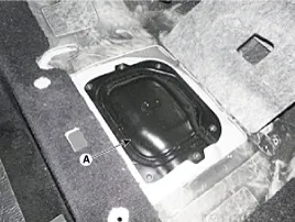
| 4. |
Remove the service cover (A) of the fuel pump after loosening the screws.
|
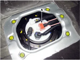
| 5. |
Disconnect the fuel feed tube quick - connector (A).
|
| 6. |
Lift the vehicle. |
| 7. |
Remove the rear-RH wheel, tire and inner wheel house. |
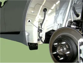
| 8. |
Disconnect the fuel tank extension connector (A), and then remove the wiring harness from the vehicle.
|
| 9. |
Remove the center muffler assembly.
(Refer to Engine Mechanical System - "Muffler") |
| 10. |
Remove the propeller shaft assembly.
(Refer to Driveshaft and Axle - "Propeller shaft Assembly") |
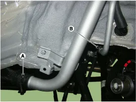
| 11. |
Disconnect the fuel filler hose (A) and leveling hose (B).
|
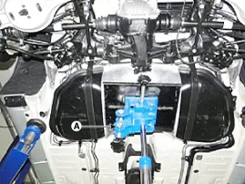
| 12. |
Support the fuel tank with jack (A).
|
| 13. |
Remove the fuel tank installation nut (A) and then loosen the fuel tank (B).
|
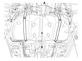
| 14. |
Disconnect the vent hose (A) and then remove the fuel tank.
|
| Installation |
| 1. |
To install, reverse the removal procedure.
|
Fuel Pressure Test 1. Release the residual pressure in fuel line. (Refer to Fuel Delivery System - "Release Residual Pressure in Fuel Line") When removing the fuel pump relay, a Diagnostic Trouble Code (DTC) may turn up.
Removal 1. Release the residual pressure in fuel line. (Refer to Fuel Delivery System - "Release Residual Pressure in Fuel Line") 2. Fold the rear seat cushion.
Other information:
Hyundai Genesis (DH) 2013-2016 Service Manual: Components and Components Location
S
Hyundai Genesis (DH) 2013-2016 Service Manual: Troubleshooting
Troubleshooting Problem Symptoms Table Before replacing or repairing air conditioning components, first determine if the malfunction is due to the refrigerant charge, air flow or compressor. Use the table below to help you find the cause of the problem.
Categories
- Manuals Home
- Hyundai Genesis Owners Manual
- Hyundai Genesis Service Manual
- Restraint
- Electric Parking Brake (EPB) Repair procedures
- Repair procedures
- New on site
- Most important about car

Copyright © 2026 www.hgenesisdh.com - 0.0253