
Hyundai Genesis (DH): AVN System / External AMP Repair procedures
| Removal |
| 1. |
Disconnect the negative (-) battery terminal. |
| 2. |
Open the trunk, remove the left trunk trim.
(Refer to Body - "Trunk Trim") |
| 3. |
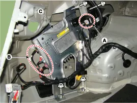
Remove the external amplifier (C) after disconnecting the connector (A),(B) and loosening the mounting nuts.
|
| Installation |
| 1. |
Install the external amplifier after connecting the connector. |
| 2. |
Install the left trunk trim. |
| 3. |
Connect the negative (-) battery terminal.
|

| Inspection |
| 1. |
In the body electrical system, failure can be quickly diagnosed by using the vehicle diagnostic system (GDS).
The diagnostic system(GDS) provides the following information.
|
| 2. |
Select the 'Car model' and the system to be checked in order to check the vehicle with the tester. |
| 3. |
Select the 'AVN' to check the AVN. |
| 4. |
Select the 'Current data" menu to search the current state of the input/output data.
The input/output data for the sensors corresponding to the AVN can be checked. |
| 5. |
To forcibly actuate the input value of the module to be checked, select option "Actuation test". |
Components NO.Connector ANO.Connector BNO.Connector C1B (+)1-1Right side low (+)2B (+)2-2Left side low (+)3B (+)3-3Right front midrange/tweeter (+)4-4-4Left front midrange/tweeter (+)5Multimedia-CAN (high)5-5Right front door (+)6Multimedia-CAN (low)6-6Left front door (+)7ACC7-7Right side low (-)8-8-8Left side low (-)9-9-9Right front midrange/tweeter (-)10-10-10Left front midrange/tweeter (-)11NAVI sound (+)11-11Right front door (-)12Sub woofer 2 (+)12-12Left front door (-)13Sub woofer 1 (+)13-1314GND14-1415GND15-1516GND16-1617-171718SPDIF (+)181819SPDIF (-)191920SPDIF GND(shield)202021-212122-222223-2324NAVI sound (-)2425Sub woofer 2 (-)2526Sub woofer 1 (-)26
Components 1. Left Top Remote Control Switch(Audio)2. Right Top Remote Control Switch(Cruise+Trip Computer)
Other information:
Hyundai Genesis (DH) 2013-2016 Service Manual: Blind Spot Detection Unit Repair procedures
Removal 1. Disconnect the negative (-) battery terminal. 2. Remove the rear bumper. (Refer to Body - "Rear Bumper") 3. Remove the BSD unit (A) after loosening the mounting nuts. Take care not to separate the bracket from rear bumper when removing the BSD sensor.
Hyundai Genesis (DH) 2013-2016 Service Manual: Compressor Components and Components Location
C
Categories
- Manuals Home
- Hyundai Genesis Owners Manual
- Hyundai Genesis Service Manual
- Description and Operation
- Suspension System
- Restraint
- New on site
- Most important about car
