
Hyundai Genesis (DH): Seat Electrical / Climate Seat Unit Repair procedures
Hyundai Genesis (DH) 2013-2016 Service Manual / Body Electrical System / Seat Electrical / Climate Seat Unit Repair procedures
| Removal |
[Front seat - ventilation blower Seat]
| 1. |
Disconnect the battery(-) terminals. |
| 2. |
Remove the front seat.
(Refer to Body - "Front Seat Assembly" ) |
| 3. |
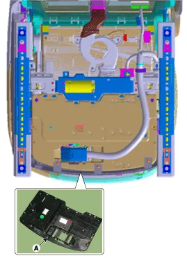
Remove the front seat undercover (A) after loosening the mounting screws.
|
| 4. |
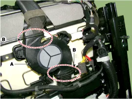
Remove the blower fan (A) after disengaging the retaining clips and mounting clip from the front seat cushion.
|
| 5. |
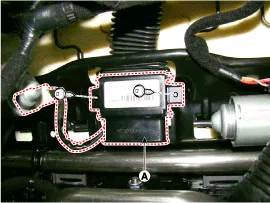
Remove the seat cushion TED (A) after loosening the screws.
|
| 6. |
Remove the front seat back board.
(Refer to Body - "Front Seat Back Board." ) |
| 7. |
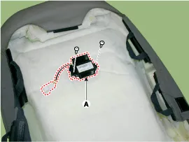
Remove the TED (A) after disconnecting the connector and loosening the screw from the seat back.
|
| 8. |
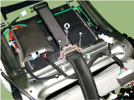
Remove the duct (A) after loosening the screw and removing retaining clip from the seat back.
|
| 9. |
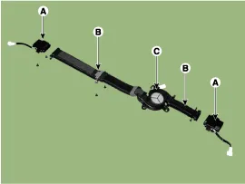
Remove the TED (A), duct (B) and the FAN (C).
|
[Front Seat - Ventilated seat unit]
| 1. |
Disconnect the battery(-) terminals. |
| 2. |
Remove the front seat.
(Refer to Body - "Front seat Assembly") |
| 3. |
Remove the front seat under cover (A) after loosening the mounting screws.
|
| 4. |
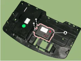
Remove the ventilation seat unit (A) after disconnecting the connector and loosening the screws.
|
| Installation |
[Front Seat - Climate control system Seat Blower ]
| 1. |
Connect the connector and then install the TED and climate control system duct on the side of the seat back. |
| 2. |
Install the front seat back board. |
| 3. |
Install the blower fan by connecting it to the connector and fixed clip under the front seat cushion. |
| 4. |
Install the TED on the seat cushion. |
| 5. |
Install the front seat cushion. |
| 6. |
Install the front seat. |
| 7. |
Connect the negative (-) battery terminal. |
[Front Seat - Climate control system Seat Unit ]
| 1. |
Install the climate control system seat unit after connecting the connectors. |
| 2. |
Install the front seat. |
| 3. |
Connect the negative (-) battery terminal. |
| Inspection |
Ventilating seat consists of three units: the ventilating seat unit for control, switch for input and and blower for output.
How to check
| 1. |
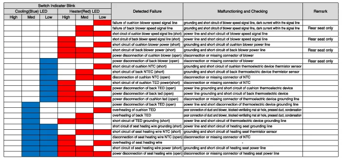
When a displaying lamp blinks indicating malfunctioning, you can refer to the following table for maintenance.
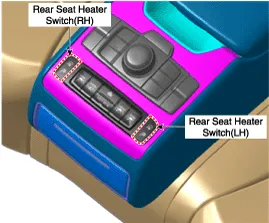
[Front Seat]
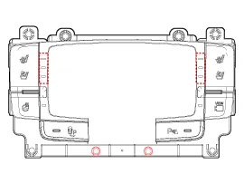
[Rear Seat]
[Failure Indicator Switch]
|
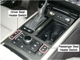
Description Comparing with the seat heat function by the existing thermic rays, Climate Control Seat functions the heating, cooling, dehumidifying by using TED.
Component Location Air lumbar support & bolster assembly Mechanical lumbar support assembly
Other information:
Hyundai Genesis (DH) 2013-2016 Service Manual: Description and Operation
Description System Overview The System offers the following features: - Changing the state of engine ignition and power by using the start button. - Controlling external relays for ACC / IGN1 / IGN2 terminal switching and STARTER, without use of mechanical ignition switch.
Hyundai Genesis (DH) 2013-2016 Service Manual: Ambient Temperature Sensor Repair procedures
I
Categories
- Manuals Home
- Hyundai Genesis Owners Manual
- Hyundai Genesis Service Manual
- Electric Parking Brake (EPB) Repair procedures
- Engine Mechanical System
- Starter Repair procedures
- New on site
- Most important about car

Copyright В© 2026 www.hgenesisdh.com - 0.0302