
Hyundai Genesis (DH): Body Dimensions / Body Panel Gaps Body Repair
Hyundai Genesis (DH) 2013-2016 Service Manual / Body (Interior and Exterior) / Body Dimensions / Body Panel Gaps Body Repair
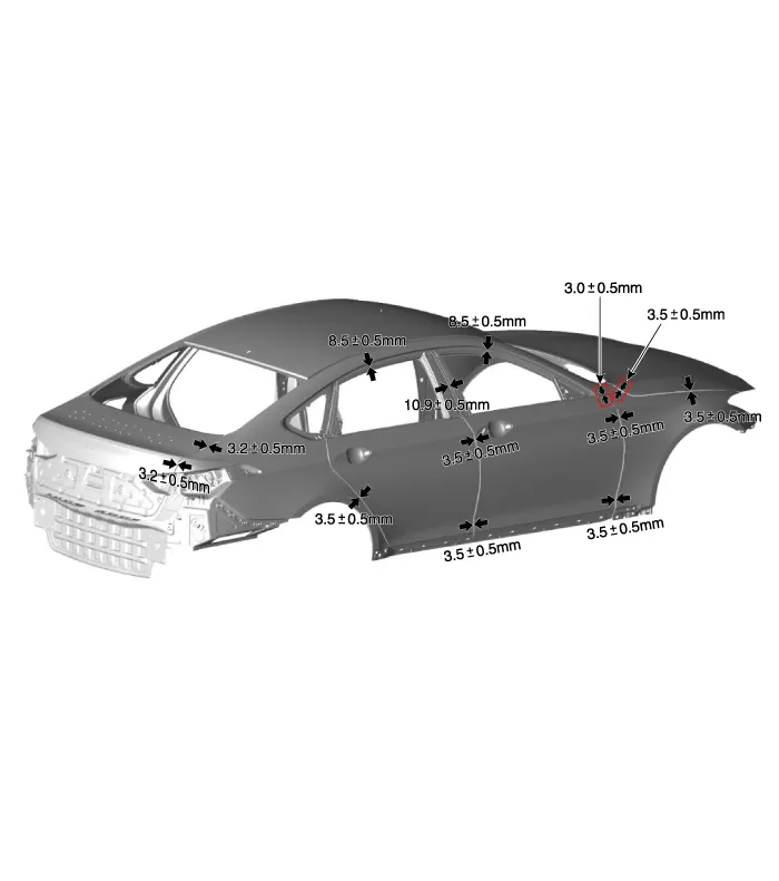
Front Cross Member * These dimensions indicated in this figure are actual-measurement dimensions. [ Unit : mm (inch) ] * These dimensions indicated in this figure are actual-measurement dimensions.
Other information:
Hyundai Genesis (DH) 2013-2016 Service Manual: Compressor Description and Operation
Description The compressor is the power unit of the A/C system. It is located on the side of engine block and driven by a V-belt of the engine. The compressor changes low-pressure and low-temperature refrigerant gas into high-pressure and high-temperature refrigerant gas.
Hyundai Genesis (DH) 2013-2016 Service Manual: Blower Motor Repair procedures
Inspection 1. Connect the battery voltage and check the blower motor rotation. 2. If the blower motor does not operate well, replace it with a genuine blower motor check for proper operation. 3. Replace the blower motor if it is proved that there is a problem with it.
Categories
- Manuals Home
- Hyundai Genesis Owners Manual
- Hyundai Genesis Service Manual
- Description and Operation
- Body Electrical System
- Brake System
- New on site
- Most important about car

Copyright В© 2026 www.hgenesisdh.com - 0.0248