Hyundai Genesis (DH): Engine Control System / Heated Oxygen Sensor (HO2S) Troubleshooting
Hyundai Genesis (DH) 2013-2016 Service Manual / Engine Control / Fuel System / Engine Control System / Heated Oxygen Sensor (HO2S) Troubleshooting
| Signal Waveform |
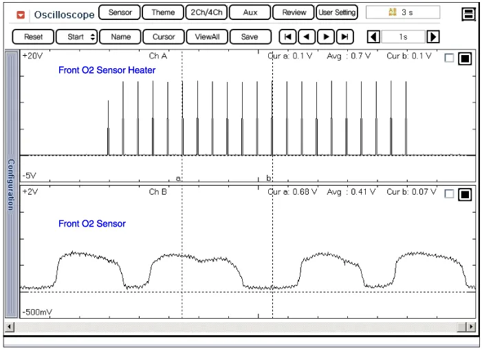
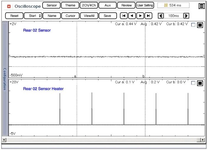
Specification A/F Ratio (?)Output Voltage(V)RICHMin. 0.8LEANMax. 0.1 ItemSpecificationHeater Resistance (?)3.0 ~ 4.1 [20
Circuit Diagram
Categories
- Manuals Home
- Hyundai Genesis Owners Manual
- Hyundai Genesis Service Manual
- Emission Control System
- Engine Mechanical System
- Brake System
- New on site
- Most important about car

Copyright © 2026 www.hgenesisdh.com - 0.0272