Hyundai Genesis (DH): Engine Control System / Fuel Tank Pressure Sensor (FTPS) Schematic Diagrams
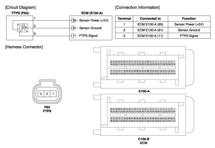
| Circuit Diagram |
Specifications Pressure [kPa (kgf/cm?, in H2O)Output Voltage (V)'-6.67 (-0.068, -26.8)0.502.5'+6.67 (0.068, 26.8)4.5
Inspection 1. Connect the GDS on the Data Link Connector (DLC ). 2. Measure the output voltage of the FTPS. Specification: Refer to "Specification" Removal 1.
Other information:
Hyundai Genesis (DH) 2013-2016 Service Manual: Auto Light Sensor Repair procedures
Removal 1. Disconnect the negative (-) battery terminal. 2. Remove the photo & auto light sensor. (Refer to Windshield Wiper/Washer - "Rain Sensor") Installation 1. Install the auto light sensor. 2. Connect the negative (-) battery terminal.
Hyundai Genesis (DH) 2013-2016 Service Manual: A/C Pressure Transducer Description and Operation
Description The A/C Pressure Transducer (APT) converts the pressure value of high-pressure line into voltage value after measuring it. By converted voltage value, engine ECU controls the cooling fan by operating it at high speed or low speed.
Categories
- Manuals Home
- Hyundai Genesis Owners Manual
- Hyundai Genesis Service Manual
- Description and Operation
- Smart Cruise Control Unit Repair procedures
- Body Electrical System
- New on site
- Most important about car
