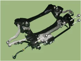
Hyundai Genesis (DH): Front Suspension System / Front Stabilizer Bar Repair procedures
| Removal |
| 1. |
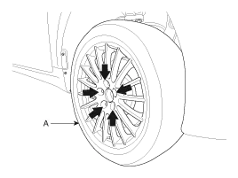
Loosen the wheel nuts slightly. Raise the vehicle, and make sure it is securely supported. |
| 2. |
Remove the front wheel and tire (A) from the front hub.
|

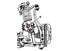
| 3. |
Loosen the nut (A) and disconnect the stabilizer link from the front strut assembly.
[ECS]
[HPD]
|
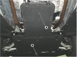
| 4. |
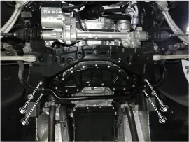
Remove the under cover (A) & (B).
|
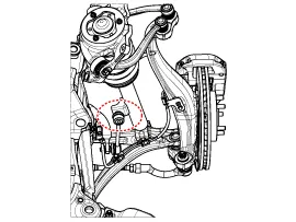
| 5. |
Loosen clamp mounting bolts and then separate the stabilizer bar from the subframe.
[4WD]
[2WD]
|
| 6. |
Install in the reverse order of removal. |
| 7. |
Check the alignment.
(Refer to Tires/Wheels - "Alignment") |
| Inspection |
| 1. |
Check the bushing for wear and deterioration. |
| 2. |
Check the ball joint for rotating torque. |
Replacement [4WD] Remove the lateral arm 1. Loosen the wheel nuts slightly. Raise the vehicle, and make sure it is securely supported. 2. Remove the front wheel and tire (A) from the front hub.
Removal 1. Loosen the wheel nuts slightly. Raise the vehicle, and make sure it is securely supported. 2. Remove the front wheel and tire (A) from the front hub.
Other information:
Hyundai Genesis (DH) 2013-2016 Service Manual: Description and Operation
Description Integrated Rain Sensor Integrated rain sensor (A) controls three systems: front wiper, auto-light, and central air conditioner. 1. Wiper Control System When "AUTO" switch signal is received from the multi-function switch on the right, the integrated rain sensor detects the amount of rainfall.
Hyundai Genesis (DH) 2013-2016 Service Manual: Blower Motor Repair procedures
Inspection 1. Connect the battery voltage and check the blower motor rotation. 2. If the blower motor does not operate well, replace it with a genuine blower motor check for proper operation. 3. Replace the blower motor if it is proved that there is a problem with it.
Categories
- Manuals Home
- Hyundai Genesis Owners Manual
- Hyundai Genesis Service Manual
- Suspension System
- Body (Interior and Exterior)
- Description and Operation
- New on site
- Most important about car
