Hyundai Genesis (DH): AVN System / External AMP Repair procedures
| Removal |
| 1. |
Disconnect the negative (-) battery terminal. |
| 2. |
Open the trunk, remove the left trunk trim.
(Refer to Body - "Trunk Trim") |
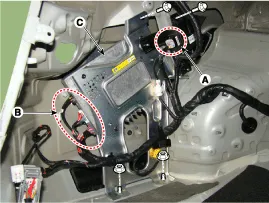
| 3. |
Remove the external amplifier (C) after disconnecting the connector (A),(B) and loosening the mounting nuts.
|
| Installation |
| 1. |
Install the external amplifier after connecting the connector. |
| 2. |
Install the left trunk trim. |
| 3. |
Connect the negative (-) battery terminal.
|

| Inspection |
| 1. |
In the body electrical system, failure can be quickly diagnosed by using the vehicle diagnostic system (GDS).
The diagnostic system(GDS) provides the following information.
|
| 2. |
Select the 'Car model' and the system to be checked in order to check the vehicle with the tester. |
| 3. |
Select the 'AVN' to check the AVN. |
| 4. |
Select the 'Current data" menu to search the current state of the input/output data.
The input/output data for the sensors corresponding to the AVN can be checked. |
| 5. |
To forcibly actuate the input value of the module to be checked, select option "Actuation test". |
Components NO.Connector ANO.Connector BNO.Connector C1B (+)1-1Right side low (+)2B (+)2-2Left side low (+)3B (+)3-3Right front midrange/tweeter (+)4-4-4Left front midrange/tweeter (+)5Multimedia-CAN (high)5-5Right front door (+)6Multimedia-CAN (low)6-6Left front door (+)7ACC7-7Right side low (-)8-8-8Left side low (-)9-9-9Right front midrange/tweeter (-)10-10-10Left front midrange/tweeter (-)11NAVI sound (+)11-11Right front door (-)12Sub woofer 2 (+)12-12Left front door (-)13Sub woofer 1 (+)13-1314GND14-1415GND15-1516GND16-1617-171718SPDIF (+)181819SPDIF (-)191920SPDIF GND(shield)202021-212122-222223-2324NAVI sound (-)2425Sub woofer 2 (-)2526Sub woofer 1 (-)26
Components 1. Left Top Remote Control Switch(Audio)2. Right Top Remote Control Switch(Cruise+Trip Computer)
Other information:
Hyundai Genesis (DH) 2013-2016 Service Manual: PGS Unit (Back & Blinde Unit) Repair procedures
Removal 1. Disconnect the negative (-) battery terminal. 2. Remove the glove box housing (A). (Refer to Body - "Glove Box") 3. Remove the PGS unit (A) after loosening the nuts. Installation 1. Install the PGS unit. 2. Install the glove box housing.
Hyundai Genesis (DH) 2013-2016 Service Manual: Photo Sensor Repair procedures
Inspection 1. Turn the ignition switch ON. 2. Connect the GDS. 3. Emit intensive light toward the photo sensor using a lamp, and check the output voltage change. 4. The voltage will rise with higher intensive light and fall with lower intensive light.
Categories
- Manuals Home
- Hyundai Genesis Owners Manual
- Hyundai Genesis Service Manual
- Steering System
- Components and Components Location
- Smart Cruise Control Unit Repair procedures
- New on site
- Most important about car
