Hyundai Genesis (DH): Engine Control System / ETC (Electronic Throttle Control) System Description and Operation
| Description |

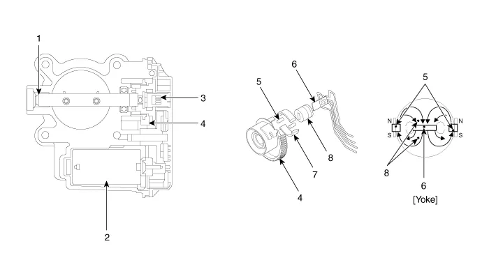
| 1. Dry bearing 2. DC motor 3. Non-contact hall sensor 4. Gear | 5. Magnet 6. Hall IC 7. Yoke 8. Stator |
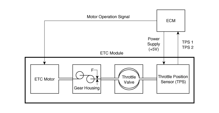
| Schematic Diagram |
Removal 1. Turn the ignition switch OFF and disconnect the battery negative (-) cable. 2. Remove the ECM & TCM & IDB bracket. (Refer to Engine Control System - "ECM") 3.
Fail-Safe Mode ItemFail-SafeETC MotorThrottle valve stuck at 7
Other information:
Hyundai Genesis (DH) 2013-2016 Service Manual: Components and Components Location
Component Location Index Engine Room [Lambda Engine] 1. Expansion Valve2. Suction & Liquid Tube Assembly3. Service Port (Low Pressure)4. Service Port (High Pressure)5. A/C Pressure Transducer (APT)6. Compressor7. Condenser8. Receiver-drier [Tau Engine] 1.
Hyundai Genesis (DH) 2013-2016 Service Manual: Photo Sensor Description and Operation
Description The photo sensor is located in the right side of the inside rearview mirror. he integrated rain sensor is located in the right side of the inside rearview mirror. The integrated rain sensor is a multifunctional sensor which combines the photo sensor and auto light sensor, and has a built-in photovoltaic diode (for detecting t
Categories
- Manuals Home
- Hyundai Genesis Owners Manual
- Hyundai Genesis Service Manual
- Restraint
- 4 Wheel Drive (AWD) System
- Transmission Control Module (TCM) Repair procedures
- New on site
- Most important about car
