Hyundai Genesis (DH): General Information / Description and Operation
Hyundai Genesis (DH) 2013-2016 Service Manual / 4 Wheel Drive (AWD) System / General Information / Description and Operation
| Description |
| 1. |
Description
 Distribution of electronically controlled driving force Distribution of electronically controlled driving force
 Mutual controlling with the related driving control system Mutual controlling with the related driving control system
|
| 2. |
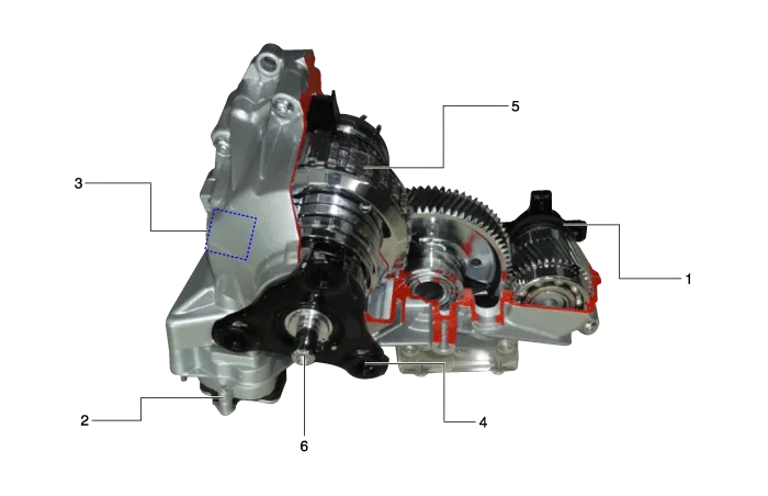
Structure of transfer case
|
| 3. |
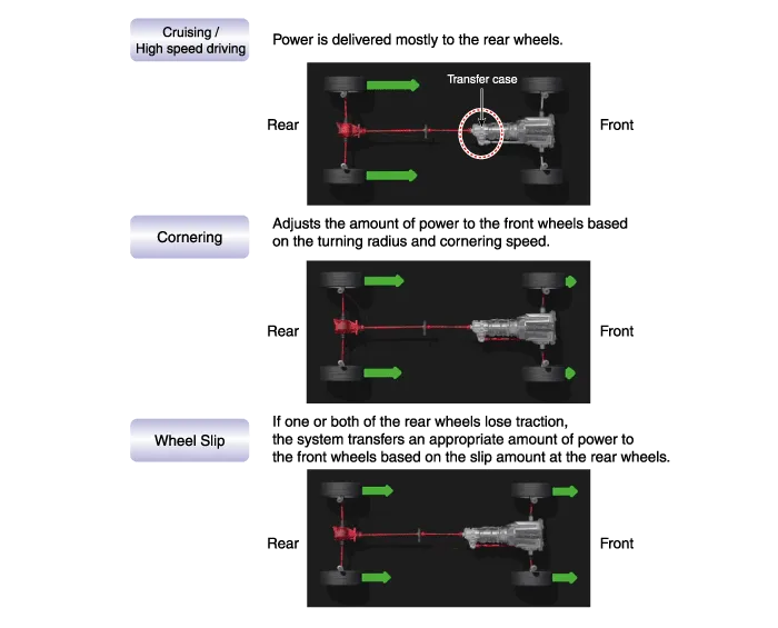
Outline of driving force distribution
|
| 4. |
Transfer case operation
1) Transfer case operation procedure
? ITA (Integrated Transfer case Actuator)
|
 Operation of Ball ramp with worm gear
 Clutch operation with Ball ramp operation
 Transmitting of torque to the gear with clutch operation
 Applying the driving force to the front wheel
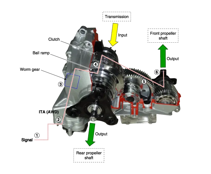
Specification ItemSpecificationProduct nameTransfer caseOperation methodElectronic actuator control method (BLDC motor)Torque capacity1,100 NmWeight25 kg (Oil injection state) Tightening Torques Item N.
Adjustment Introduction It is necessary to check and input the calibration data when the controller is replaced as the characteristics of the internal frictional materials (clutch pack) change due to driving.
Other information:
Hyundai Genesis (DH) 2013-2016 Service Manual: Blind Spot Detection Switch Repair procedures
Removal 1. Disconnect the negative (-) battery terminal. 2. Remove the crash pad lower panel. (Refer to Body - "Crash Pad") 3. Remove the blind spot detection (BSD) switch (A) after disengaging the mounting clip. Installation 1. Install the crash pad side switch assembly after connecting the connector.
Hyundai Genesis (DH) 2013-2016 Service Manual: Head Up Display Unit Troubleshooting
T
Categories
- Manuals Home
- Hyundai Genesis Owners Manual
- Hyundai Genesis Service Manual
- Emission Control System
- Heating, Ventilation and Air Conditioning
- Restraint
- New on site
- Most important about car

Copyright © 2026 www.hgenesisdh.com - 0.0279