
Hyundai Genesis (DH): Cooling System / Cooling Fan Repair procedures
Hyundai Genesis (DH) 2013-2016 Service Manual / Engine Mechanical System / Cooling System / Cooling Fan Repair procedures
| Removal And Installation |
Cooling fan
| 1. |
Disconnect the battery "-" terminal from the trunk room. |
| 2. |
Remove the air cleaner assembly.
(Refer to Intake and Exhaust System - "Air Cleaner") |
| 3. |
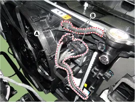
Disconnect the over flow hose (A) and cooling fan motor connector (B).
|
| 4. |
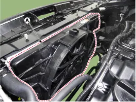
Loosen the cooling fan mounting bolts and then remove the cooling fan (A).
|
| 5. |
To install, reverse the removal procedure. |
Cooling fan controller (PWM)
| 1. |
Disconnect the battery "-" terminal from the trunk room. |
| 2. |
Remove the air cleaner assembly.
(Refer to Intake and Exhaust System - "Air Cleaner") |
| 3. |
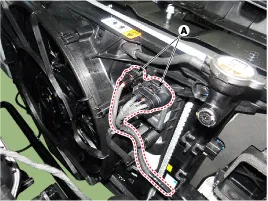
Disconnect the cooling fan motor connector (A).
|
| 4. |
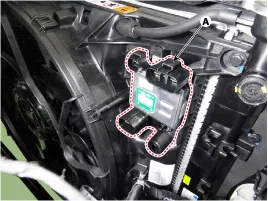
Remove the cooling fan controller (PWM) (A).
|
| 5. |
To install, reverse the removal procedure. |
| Disassembly |
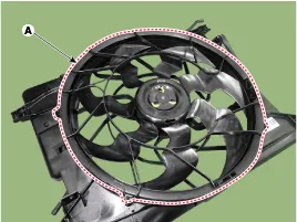
| 1. |
Remove the cooling fan rear cover (A).
|
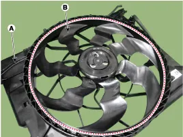
| 2. |
Remove the fan (B) from cooling fan assembly (A).
|
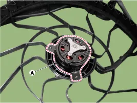
| 3. |
Remove the cooling fan motor (A).
|
| 4. |
To install, reverse the removal procedure. |
Cooling Circuit Diagram
Troubleshooting SymptomsRemedyIf the cooling fan is not functioning under normal operating conditions
Other information:
Hyundai Genesis (DH) 2013-2016 Service Manual: Specifications
S
Hyundai Genesis (DH) 2013-2016 Service Manual: Components and Components Location
Component Location Index Engine Room [Lambda Engine] 1. Expansion Valve2. Suction & Liquid Tube Assembly3. Service Port (Low Pressure)4. Service Port (High Pressure)5. A/C Pressure Transducer (APT)6. Compressor7. Condenser8. Receiver-drier [Tau Engine] 1.
Categories
- Manuals Home
- Hyundai Genesis Owners Manual
- Hyundai Genesis Service Manual
- Components and Components Location
- Active Air Flap(AAF) Repair procedures
- Front Door
- New on site
- Most important about car

Copyright В© 2026 www.hgenesisdh.com - 0.0266