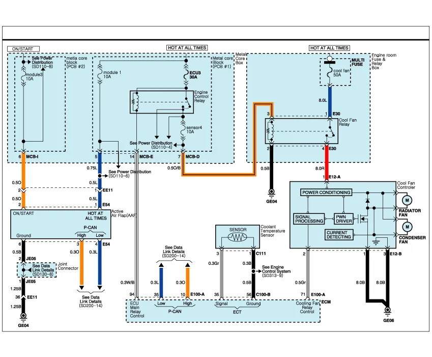
Hyundai Genesis (DH): Cooling System / Cooling Fan Schematic Diagrams
| Cooling Circuit Diagram |
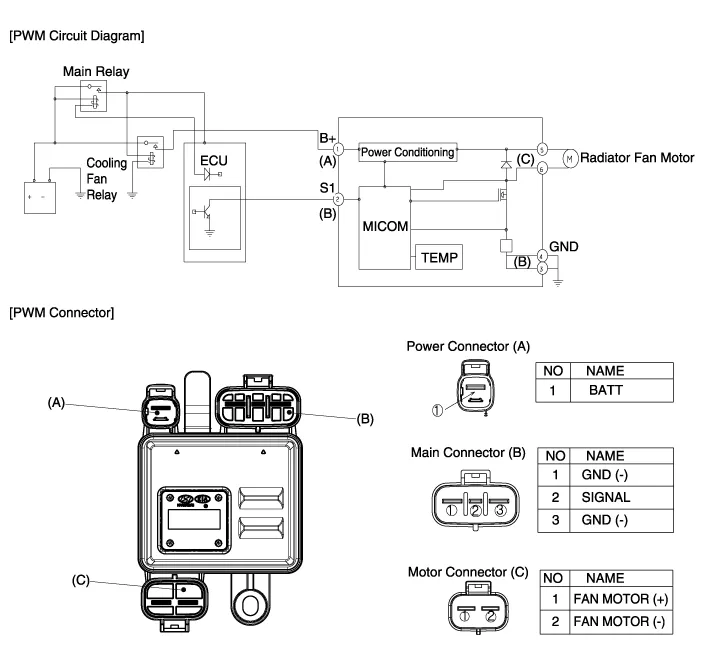
Specifications [Cooling fan control (PWM)] ItemsPerformance specMAX, load current consumption (12V)23.3 + 10% AInputCommunication frequency300
Removal And Installation Cooling fan 1. Disconnect the battery "-" terminal from the trunk room. 2. Remove the air cleaner assembly. (Refer to Intake and Exhaust System - "Air Cleaner") 3.
Other information:
Hyundai Genesis (DH) 2013-2016 Service Manual: Description and Operation
Description System Overview The System offers the following features: - Changing the state of engine ignition and power by using the start button. - Controlling external relays for ACC / IGN1 / IGN2 terminal switching and STARTER, without use of mechanical ignition switch.
Hyundai Genesis (DH) 2013-2016 Service Manual: Ambient Temperature Sensor Description and Operation
Description The ambient temperature sensor is located inside the side mirror and detects ambient air temperature. It is a negative type thermistor; resistance will increase with lower temperature, and decrease with higher temperature. The sensor output will be used for discharge temperature control, temperature regulation door control,
Categories
- Manuals Home
- Hyundai Genesis Owners Manual
- Hyundai Genesis Service Manual
- Emission Control System
- Restraint
- Suspension System
- New on site
- Most important about car
