Hyundai Genesis (DH): Cooling System / Cooling Fan Description and Operation
Hyundai Genesis (DH) 2013-2016 Service Manual / Engine Mechanical System / Cooling System / Cooling Fan Description and Operation
| Description |
The cooling fan controlsx the cooling fan motor voltage depending on the duty output from the ECU (Freq.: 300Hz).
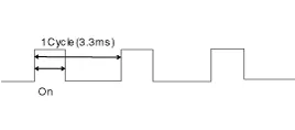
[Signal from the ECU to the PWM (SI: 300Hz)]
| SI Duty | Motor Voltage (V) | Variation (V) |
| 10% | 0 |
Components 1. Cooling fan shroud2. Cooing fan3. Cooling fan motor4. Cooling far rear cover5. Cooling fan controller (PWM)6. Reservoir tank
Specifications [Cooling fan control (PWM)] ItemsPerformance specMAX, load current consumption (12V)23.3 + 10% AInputCommunication frequency300
Other information:
Hyundai Genesis (DH) 2013-2016 Service Manual: Photo Sensor Repair procedures
Inspection 1. Turn the ignition switch ON. 2. Connect the GDS. 3. Emit intensive light toward the photo sensor using a lamp, and check the output voltage change. 4. The voltage will rise with higher intensive light and fall with lower intensive light.
Hyundai Genesis (DH) 2013-2016 Service Manual: Heater & A/C Control Unit Components and Components Location
C
Categories
- Manuals Home
- Hyundai Genesis Owners Manual
- Hyundai Genesis Service Manual
- Steering System
- Engine Electrical System
- Starter Repair procedures
- New on site
- Most important about car

Copyright © 2026 www.hgenesisdh.com - 0.0236