Hyundai Genesis (DH): Brake System / Brake Pedal Repair procedures
Hyundai Genesis (DH) 2013-2016 Service Manual / Brake System / Brake System / Brake Pedal Repair procedures
| Removal |
| 1. |
Turn ignition switch OFF and disconnect the negative (-) battery cable. |
| 2. |
Remove the crash pad lower panel.
(Refer to Body - "Crash Pad Lower Panel") |
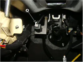
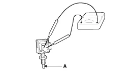
| 3. |
Disconnect the stop lamp switch connector (A).
|
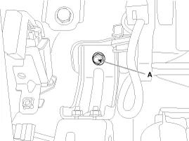
| 4. |
Remove the brake pedal member mounting nut (A).
|
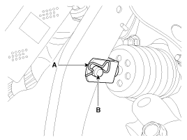
| 5. |
Remove the snap pin (A) and clevis pin (B).
|
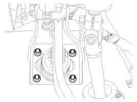
| 6. |
Remove the brake pedal member assembly mounting nuts and then remove the brake pedal assembly.
|
| Inspection |
| 1. |
Check the bushing for wear. |
| 2. |
Check the brake pedal for bending or twisting. |
| 3. |
Check the brake pedal return spring for damage. |
| 4. |
Check the stop lamp switch.
|
| Installation |
| 1. |
To install, reverse the removal procedure. |
| 2. |
Adjust the brake pedal height and free play. |
| 3. |
Check the brake pedal operation after installing the brake pedal. |
Components 1. Brake pedal member assembly2. Stop lamp switch3. Clevis pin4. Snap pin5. Brake pedal stopper6. Return spring7. Bolt
Components 1. Caliper body2. Guide pin3. Locking pin4. Brake pad5. Cover plate 6. Pad spring7. Bleed screw
Other information:
Hyundai Genesis (DH) 2013-2016 Service Manual: High Mounted Stop Lamp Repair procedures
Removal High Mounted Stop Lamp 1. Disconnect the negative (-) battery terminal. 2. Remove the roof trim assembly. (Refer to Body - "Roof Trim") 3. Remove the high mounted stop lamp assembly (A) after loosening the mounting screws. Installation 1.
Hyundai Genesis (DH) 2013-2016 Service Manual: Components and Components Location
C
Categories
- Manuals Home
- Hyundai Genesis Owners Manual
- Hyundai Genesis Service Manual
- 4 Wheel Drive (AWD) System
- Body Electrical System
- Starter Repair procedures
- New on site
- Most important about car

Copyright © 2026 www.hgenesisdh.com - 0.0238