Hyundai Genesis (DH): Charging System / Alternator Schematic Diagrams
Hyundai Genesis (DH) 2013-2016 Service Manual / Engine Electrical System / Charging System / Alternator Schematic Diagrams
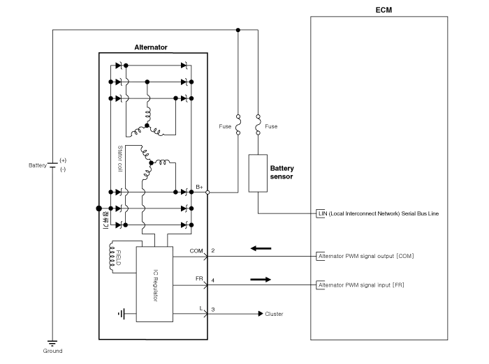
| Circuit Diagram |
Specification ItemSpecificationRated voltage13.5V , 150ASpeed in use1,500 ~ 18,000rpmVoltage regulatorIC Regulator built in typeRegulator reform mode voltage (V) [COM terminal]14. Removal 1. Turn ignition switch OFF and disconnect the negative (-) battery cable. 2. Remove the engine cover. 3. Disconnect the alternator connector (A) and cable (B) from the 'B' terminal. Other information:Hyundai Genesis (DH) 2013-2016 Service Manual: Auto Head Lamp Leveling Unit Repair proceduresInspection 1. Ignition "ON". 2. Turn on the head lamp switch. 3. Check that the aim of the head lamp changes smoothly when the head lamp leveling device switch is turned on. 4. If it does not operate well, check the connector and terminals to make sure that they are connected. Hyundai Genesis (DH) 2013-2016 Service Manual: Components and Components LocationC Categories

Copyright © 2026 www.hgenesisdh.com - 0.0182
|
