Hyundai Genesis (DH): Cooling System / Active Air Flap(AAF) Schematic Diagrams
Hyundai Genesis (DH) 2013-2016 Service Manual / Engine Mechanical System / Cooling System / Active Air Flap(AAF) Schematic Diagrams
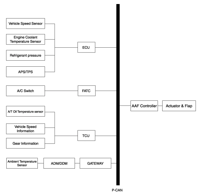
| Schematic Diagram |
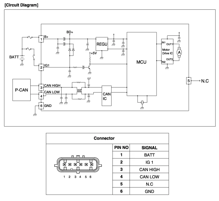
| Circuit Diagram |
Components 1. Active air housing2. Active air flap3. Active air link4. Active air actuator5. Active air duct6. Active air actuator cover
Removal and Installation 1. Disconnect the battery "-" terminal from the trunk room. 2. Remove the front bumper. (Refer to Body - "Front Bumper Cover") 3.
Other information:
Hyundai Genesis (DH) 2013-2016 Service Manual: Evaporator Temperature Sensor Repair procedures
I
Hyundai Genesis (DH) 2013-2016 Service Manual: Auto Defogging Actuator Description and Operation
Description The auto defogging sensor is installed on front window glass. The sensor judges and sends signal if moisture occurs to blow out wind for defogging. The air conditioner control module receives a signal from the sensor and restrains moisture and eliminates defog by the intake actuator, A/C, auto defogging actuator, blower motor
Categories
- Manuals Home
- Hyundai Genesis Owners Manual
- Hyundai Genesis Service Manual
- Electric Parking Brake (EPB) Repair procedures
- Restraint
- Heating, Ventilation and Air Conditioning
- New on site
- Most important about car

Copyright © 2026 www.hgenesisdh.com - 0.0275