Hyundai Genesis (DH): Engine Control System / Accelerator Position Sensor (APS) Schematic Diagrams
| Circuit Diagram |
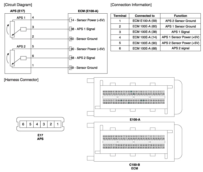
Specification AcceleratorPositionOutput Voltage (V)APS1APS2C.T0.7 ~ 0.80.33 ~ 0.43W.O.T3.85 ~ 4.351.93 ~ 2.18
Inspection 1. Connect the GDS on the Data Link Connector (DLC). 2. Turn the ignition switch ON. 3. Measure the output voltage of the APS 1 and 2 at C.
Other information:
Hyundai Genesis (DH) 2013-2016 Service Manual: Description and Operation
System Overview RPAS (Rear Parking Assist System) is an electronic driving aid that warns the driver to be cautious while parking or driving at low speed. The sensor uses ultrasonic waves to detect objects within proximity of the vehicle. RPAS consists of four RPS sensors which are detecting the obstacles and transmit the result separat
Hyundai Genesis (DH) 2013-2016 Service Manual: CO2 Sensor Description and Operation
Description This system maintains the density of carbon dioxide constantly in vehicle interior by measuring the amount of carbon dioxide to increase the comfortableness and the fuel consumption rate when air conditioning system is operating.
Categories
- Manuals Home
- Hyundai Genesis Owners Manual
- Hyundai Genesis Service Manual
- Restraint
- Parking Assist Sensor Repair procedures
- 4 Wheel Drive (AWD) System
- New on site
- Most important about car
