Hyundai Genesis (DH): Cylinder Block / Water Jacket Seperator Repair procedures
Hyundai Genesis (DH) 2013-2016 Service Manual / Engine Mechanical System / Cylinder Block / Water Jacket Seperator Repair procedures
| Removal |
| 1. |
Remove the LH/RH cylinder head assembly.
(Refer to Cylinder Head Assembly - "Cylinder Head") |
| 2. |
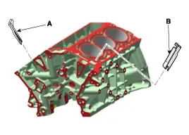
Remove the water jacket separator 1# (A) and 2# (B).
|
| Installation |
| 1. |
Install the water jacket separator 1# (A) and 2# (B).
|


| 2. |
Install the LH/RH cylinder head.
(Refer to Cylinder Head Assembly - "Cylinder Head") |
Components 1. Water jacket separator 1#2. Water jacket separator 2#3. Cylinder block
Components 1. Drive plate2. Adapter plate3. Crankshaft adapter
Other information:
Hyundai Genesis (DH) 2013-2016 Service Manual: Blind Spot Detection Indicator Components and Components Location
C
Hyundai Genesis (DH) 2013-2016 Service Manual: Blower Unit Components and Components Location
Component Location Components 1. Seal2. Intake Duct Case3. Intake Door4. Intake Actuator5. Intake Duct Case (A)6. Climate Control Air Filter7. Climate Control Air Filter Cover8. Cluster Ionizer9. Blower Upper Case10. Blower Lower Case11. Power Mosfet12.
Categories
- Manuals Home
- Hyundai Genesis Owners Manual
- Hyundai Genesis Service Manual
- Smart Cruise Control Unit Repair procedures
- Heating, Ventilation and Air Conditioning
- Suspension System
- New on site
- Most important about car

Copyright © 2026 www.hgenesisdh.com - 0.0222