Hyundai Genesis (DH): General Information / Troubleshooting
Hyundai Genesis (DH) 2013-2016 Service Manual / Engine Control / Fuel System / General Information / Troubleshooting
| Basic Troubleshooting |
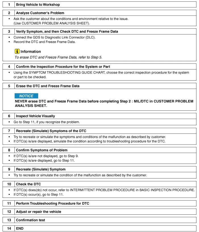
Basic Troubleshooting Guide
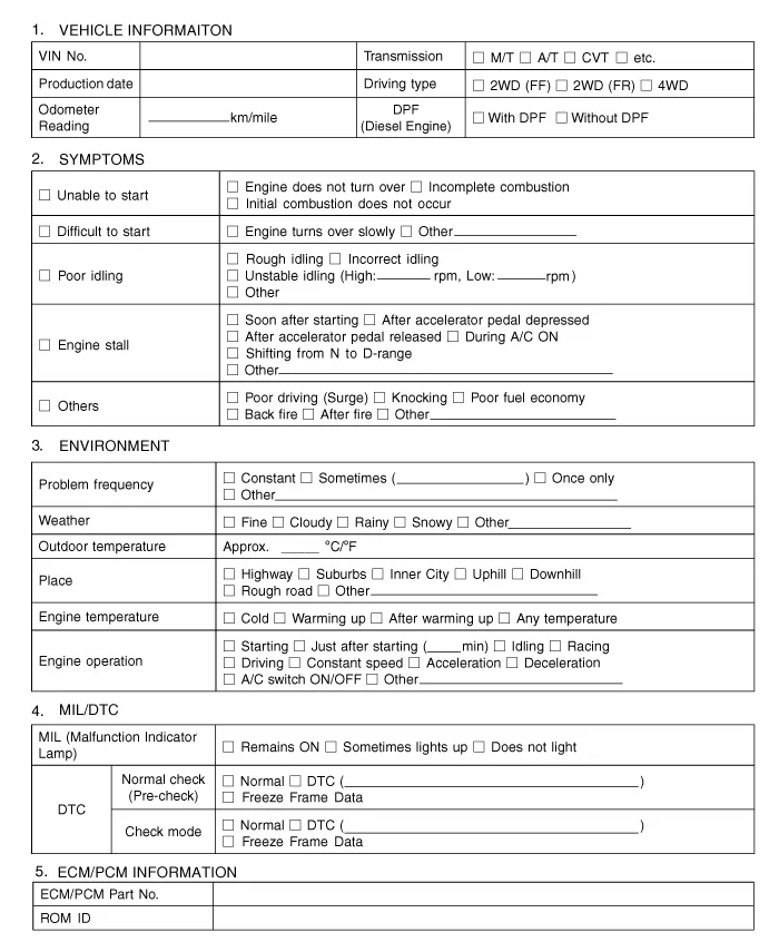
Customer Problem Analysis Sheet
Basic Inspection Procedure
Measuring Condition of Electronic Parts' Resistance
The resistance measured at high temperature after running the
vehicle may be high or low. So all resistance must be measured at
ambient temperature (20
Special Service Tools ItemIllustrationApplicationFuel Pressure Gauge(09353-24100)Measuring the fuel line pressureFuel Pressure Gauge Adapter(09353-02100)Connection between the high pressure fuel pump and the fuel feed lineHeated Oxygen Sensor Socket Wrench(09392-1Y100)Removal and installation of the heated oxygen sensor? SST No.
Categories
- Manuals Home
- Hyundai Genesis Owners Manual
- Hyundai Genesis Service Manual
- Description and Operation
- Engine Mechanical System
- Smart Cruise Control Unit Repair procedures
- New on site
- Most important about car

Copyright © 2026 www.hgenesisdh.com - 0.0299