Hyundai Genesis (DH): Brake System / Stop Signal Electronic Module Repair procedures
Hyundai Genesis (DH) 2013-2016 Service Manual / Brake System / Brake System / Stop Signal Electronic Module Repair procedures
| Inspection |
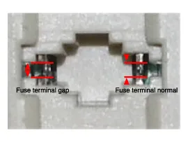
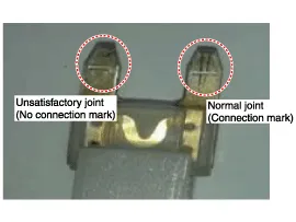
1. Fuse inspection
Install the test fuse to the switch fuse and relay fuse part in order to confirm a normal joint fit.
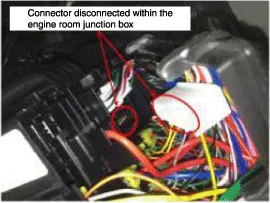
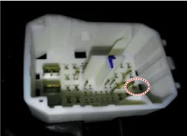
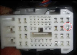
2. Inspection of connector by each part
Check whether each connector is damaged, or there is terminal surge or incomplete connection.
[Engine room junction box]
[Stop signal electronic module]
[ABS/VDC control module]
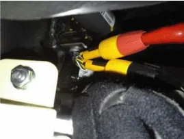
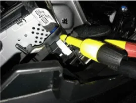
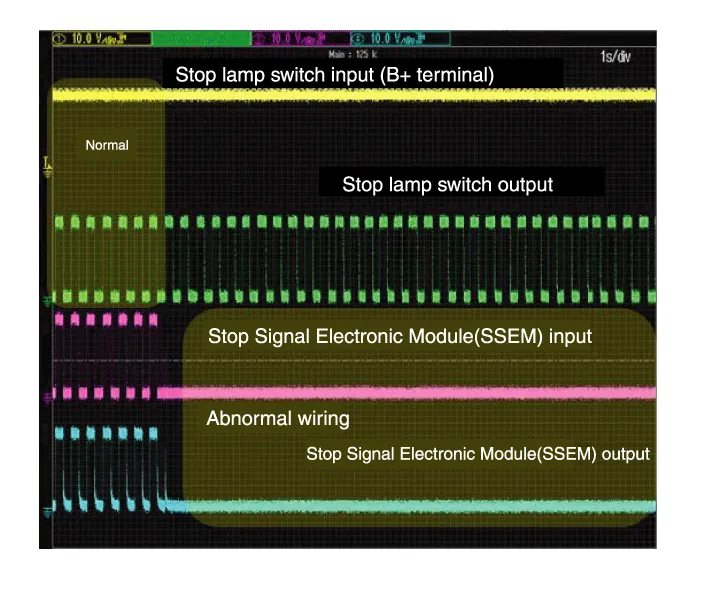
3. Inspect the stop lamp circuit
Connect probe to each terminal wire and check oscilloscope waveform.
[Stop lamp switch input/output]
[Stop signal electronic module input/output]
[Oscilloscope waveform screen]
| Removal |
| 1. |
Turn ignition switch OFF and disconnect the negative (-) battery cable. |
| 2. |
Remove the AVN unit.
(Refer to Body Electrical System - "AVN system" )
(Refer to Body Electrical System - "Premium AVN System") |
| 3. |
Remove the glove box.
(Refer to Body - "Glove Box" ) |
| 4. |
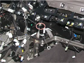
Disconnect the stop signal electronic module connector (A). |
| 5. |
Remove the clip (B) and then remove the stop signal electronic module.
|
| 6. |
To install, reverse the removal procedure. |
System Circuit Diagram Terminal Function Description1Ground 2HAC/DBC Signal (Active Low)3ESS Signal (Active Low)4Stop lamp5Stop lamp switch6ECU/ SMK7ESS Signal (Active High)8Battery
Categories
- Manuals Home
- Hyundai Genesis Owners Manual
- Hyundai Genesis Service Manual
- General Information
- Restraint
- Brake System
- New on site
- Most important about car

Copyright © 2025 www.hgenesisdh.com - 0.0227