Hyundai Genesis: Motor Driven Power Steering / Steering Column and Shaft Repair procedures
1. |
Disconnect the battery negative cable from the battery and then wait for at least 30 seconds. |
2. |
Turn the steering wheel so that the front wheels are placed in the straight ahead position. |
3. |
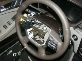
Remove the airbag module.
(Refer to Restraint - "Driver Airbag (DAB) Module and Clock Spring") |
4. |
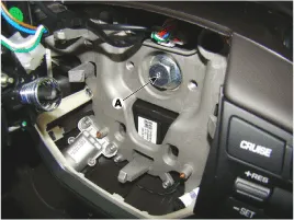
Disconnect the connector & lock bolt (A) and then remove the steering wheel by using special service tools (09561-11001).
Tightening Torques :
39.2 ~ 49.0N.m (4.0 ~ 5.0 kgf.m, 28.9 ~ 36.2lb-ft)
|


Tighten the lock bolt appropriately and install the SST (09561-1101) in order to separate the steering wheel easily. |
• |
Do not use a hammer to remove the steering wheel because it may damage the steering column. |
• |
When installing, do not reuse the steering lock bolt. |
|
|
5. |
Remove the steering column shroud.
(Refer to Body (Interior and Exterior) - "Steering Column Shroud Panel") |
6. |
Remove the clock spring.
(Refer to Restraint - "Driver Airbag (DAB) Module and Clock Spring") |
7. |
Remove the multifunction switch.
(Refer to Body Electrical System - "Multifunction switch") |
8. |
Remove the crash pad lower panel.
(Refer to Body (Interior and Exterior) - "Crash Pad Lower Panel") |
9. |
Remove the knee airbag and disconnect the connector. 
|
10. |
Unscrew the steering column bolt (A) to disconnect the universal joint and steering gear connection.
Tightening Torques :
32.4 ~ 37.3N.m (3.3 ~ 3.8 kgf.m, 23.9 ~ 27.5lb-ft)
|

Do not reuse the universal joint bolt, Be sure to install a new one. |
|
11. |
Loosen the bolt (A) & (B) and remove the steering column assembly.
Tightening Torques :
Nut : 12.7 ~ 17.7N.m (1.3 ~ 1.8 kgf.m, 9.4 ~ 13.0lb-ft)
bolt : 44.1~49.0 N.m(4.0~4.5 kgf.m, 32.5~36.2 lb-ft)
|


|
12. |
Install in the reverse order of removal. |
Universal joint assembly
1. |
Unscrew the steering column bolt (A) to disconnect the universal joint and steering gear connection.
Tightening Torques :
32.4 ~ 37.3N.m (3.3 ~ 3.8 kgf.m, 23.9 ~ 27.5lb-ft)
|

Do not reuse the universal joint bolt, Be sure to install a new one. |
|
2. |
Loosen the nut (A) and remove the dust cover (B).
Tightening Torques :
32.4 ~ 37.3N.m (3.3 ~ 3.8 kgf.m, 23.9 ~ 27.5lb-ft)
|

|
3. |
Raise the vehicle, and make sure it is securely supported. |
4. |
Remove the under cover (A), (B). 
|
5. |
Unscrew the interior universal joint column bolt (A) and remove the universal joint assembly.
Tightening Torques :
32.4 ~ 37.3N.m (3.3 ~ 3.8 kgf.m, 23.9 ~ 27.5lb-ft)
|
[LHD] 
[RHD] 
Do not reuse the universal joint bolt, Be sure to install a new one. |
|
6. |
Install in the reverse order of removal. |
1. |
Check the steering column for damage and deformation. |
2. |
Check the joint bearing for damage and wear. |
3. |
Check the tilt bracket for damage and cracks. |
4. |
Check the key lock assembly for proper operation and replace it if necessary |
Circuit Diagram
1.
Connector terminal
TypePin NoDescriptionBattery1Battery -2Battery +Vhicle1-2-3-4-5-6-7IGN8High_CAN9Low_CAN10-11-12-
2.
Circuit Diagram ...
Components Location
[4WD]
1. Steering gear box2. Motor3. ECU4. Sub frame5. Knuckle
[2WD]
1. Steering gear box2. Motor3. ECU4. Sub frame
...
Other information:
WARNING
Tire failure may cause loss of
vehicle control resulting in an
accident. To reduce risk of
SERIOUS INJURY or DEATH,
take the following precautions:
Inspect your tires monthly for
proper inflation as well as
wear and damage.
The recommended cold tire
pressure for your ...
Replacement
1.
Disconnect the negative (-) battery terminal.
2.
Remove the roof trim assembly.
(Refer to Body - "Roof Trim")
3.
Remove the panorama sunroof motor (A) after loosening the screws and disconnecting the connector.
4.
Remove the roller blind motor (A) after loosening the ...