Hyundai Genesis (DH): Smart Key System / Smart Key Repair procedures
| Smart Key |
| 1. |
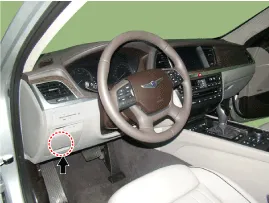
Connect the DLC cable of GDS to the data link connector (16 pins) in driver side crash pad lower panel, turn the power on GDS.
|
| 2. |
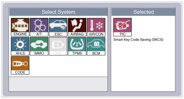
Select the vehicle model and then do "Smart key code saving".
|
| 3. |
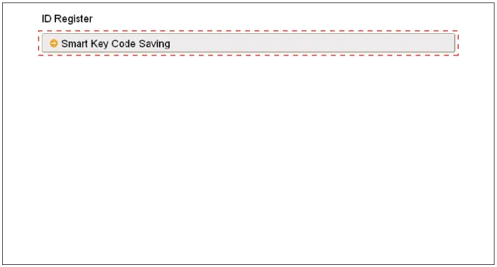
After selecting "Smart key teaching" menu, push "Enter" key, then the screen will be shown as below.
|
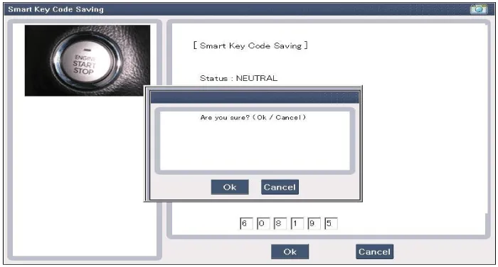
| 4. |
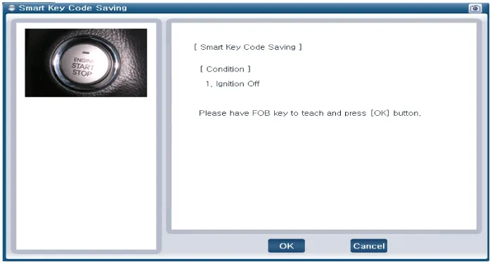
After having the teaching smart key, push "ENTER" key. |
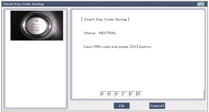
| 5. |
Input the "Pin code" for first key teaching.
|
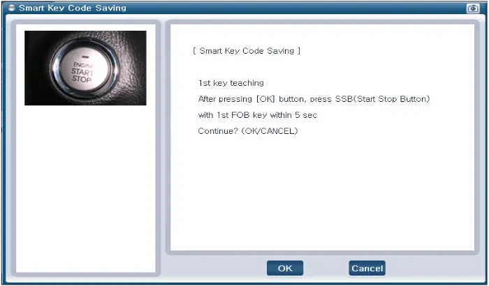
| 6. |
Press the SSB with smart key within 5 sec after pressing "OK".
|
| 7. |
Confirm the message "First key teaching completed".
|
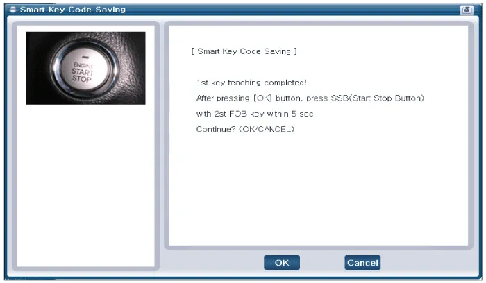
| 8. |
Press the SSB with smart key within 5 sec after pressing "OK".
|
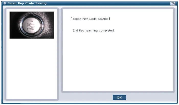
| 9. |
Confirm the message "Second key teaching completed".
|
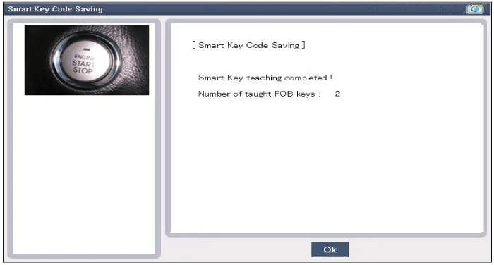
| 10. |
Then the screen will be shown as below when key teaching process is completed.
|
Description Refer to the "Body Network System" for the abbreviation information. The SMART KEY system is a system that allows the user to access and operate a vehicle in a very convenient way.
Components (1) NO.Connector AConnector BConnector C1Immobilizer antenna GNDB+IGN2 input2Bumper antenna GND??3Trunk antenna GNDESCL GRN ESCL enable output4Indoor antenna 2 GND?Assist door button input5Driver's door antenna GNDGNDSSB_switch1 inpuf6Indoor antenna 1 GNDB+POWEREMS CAN7Door antenna assist GND?RPM signal inpuf8SSB_LED OFF outputESCL BAT Wheel speed input9SSB_LED ACC output?Start Feedback signal inpuf10SSB_LED IGN outputGNDBrake switch signal input (Normal Open)11SSB LED POWER?P signal input (AT specification)12??ESCL unlock signal input13Immobilizer antenna power??14Bumper antenna power??15Trunk antenna power??16Indoor antenna 2 power? SSB switch2 inpuf17Driver's door antenna power??18Indoor antenna 1 power??19Assist door antenna power?B CAN LOW20IGN2 relay output?B CAN HIGH21IGN2 relay output?Driver's door switch input22ACC relay output??23SSB LED GND? ESCL CAN24Starter relay output??25???26??ACC 27??IGN2
Other information:
Hyundai Genesis (DH) 2013-2016 Service Manual: Components and Components Location
C
Hyundai Genesis (DH) 2013-2016 Service Manual: Auto Defogging Actuator Repair procedures
Inspection 1. Turn the ignition switch OFF. 2. Disconnect the auto defogging connector. 3. Verify that the auto defogging actuator operates to the open position when connecting 12V to terminal 3 and grounding terminal 4. Verify that the auto defogging actuator operates to the close position when connected in reverse.
Categories
- Manuals Home
- Hyundai Genesis Owners Manual
- Hyundai Genesis Service Manual
- Description and Operation
- Suspension System
- Transmission Control Module (TCM) Repair procedures
- New on site
- Most important about car
