Hyundai Genesis (DH): Smart Key System / Smart Key Unit Components and Components Location
| Components (1) |
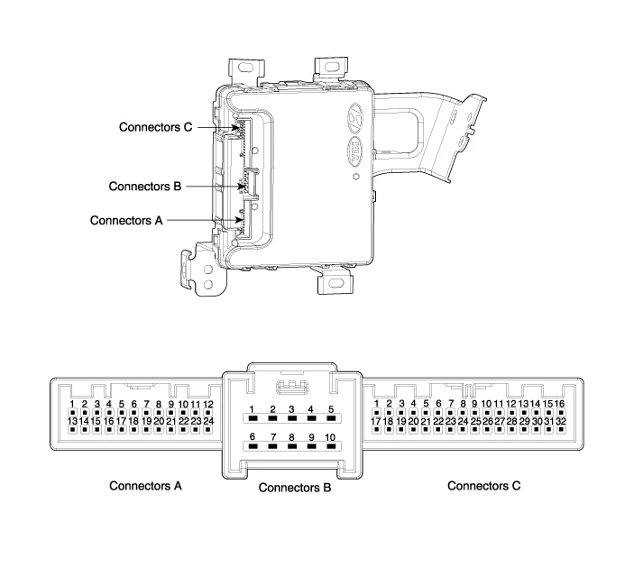
| NO. | Connector A | Connector B | Connector C | |||
| 1 | Immobilizer antenna GND | B+ | IGN2 input | |||
| 2 | Bumper antenna GND | ? | ? | |||
| 3 | Trunk antenna GND | ESCL GRN | ESCL enable output | |||
| 4 | Indoor antenna 2 GND | ? | Assist door button input | |||
| 5 | Driver's door antenna GND | GND | SSB_switch1 inpuf | |||
| 6 | Indoor antenna 1 GND | B+POWER | EMS CAN | |||
| 7 | Door antenna assist GND | ? | RPM signal inpuf | |||
| 8 | SSB_LED OFF output | ESCL BAT | Wheel speed input | |||
| 9 | SSB_LED ACC output | ? | Start Feedback signal inpuf | |||
| 10 | SSB_LED IGN output | GND | Brake switch signal input (Normal Open) | |||
| 11 | SSB LED POWER | ? | P signal input (AT specification) | |||
| 12 | ? | ? | ESCL unlock signal input | |||
| 13 | Immobilizer antenna power | ? | ? | |||
| 14 | Bumper antenna power | ? | ? | |||
| 15 | Trunk antenna power | ? | ? | |||
| 16 | Indoor antenna 2 power | ? | SSB switch2 inpuf | |||
| 17 | Driver's door antenna power | ? | ? | |||
| 18 | Indoor antenna 1 power | ? | ? | |||
| 19 | Assist door antenna power | ? | B CAN LOW | |||
| 20 | IGN2 relay output | ? | B CAN HIGH | |||
| 21 | IGN2 relay output | ? | Driver's door switch input | |||
| 22 | ACC relay output | ? | ? | |||
| 23 | SSB LED GND | ? | ESCL CAN | |||
| 24 | Starter relay output | ? | ? | |||
| 25 | ? | ? | ? | |||
| 26 | ? | ? | ACC | |||
| 27 | ? | ? | IGN2 | |||
Smart Key Smart Key Code Saving 1. Connect the DLC cable of GDS to the data link connector (16 pins) in driver side crash pad lower panel, turn the power on GDS.
Circuit Diagram
Other information:
Hyundai Genesis (DH) 2013-2016 Service Manual: Front Fog Lamps Repair procedures
Removal 1. Disconnect the negative (-) battery terminal. 2. Remove the front bumper. (Refer to Body - "Front Bumper Cover") 3. Disconnect the front fog lamp connector (A). 4. Remove the front fog lamp assembly (A) after loosening the mounting nut.
Hyundai Genesis (DH) 2013-2016 Service Manual: Auto Defogging Sensor Description and Operation
Description The auto defogging sensor is installed on the front window glass. The sensor judges and sends signal if moisture occurs to blow out wind for defogging. The air conditioner control module receives signal from the sensor and restrains moisture and eliminate defog by controlling the intake actuator, A/C, auto defogging actuator,
Categories
- Manuals Home
- Hyundai Genesis Owners Manual
- Hyundai Genesis Service Manual
- Brake System
- Steering System
- Emission Control System
- New on site
- Most important about car
