Hyundai Genesis (DH): Seat Electrical / Seat heater switch Repair procedures
Hyundai Genesis (DH) 2013-2016 Service Manual / Body Electrical System / Seat Electrical / Seat heater switch Repair procedures
| Removal |
Front Seat
| 1. |
Disconnect the battery (-)terminals. |
| 2. |
Remove the floor console upper cover.
(Refer to Body - "Floor Console Assembly")
|
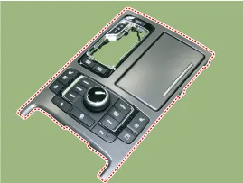
| 3. |
Disconnect the connecter and screw and remove the seat heater switch assembly (A).
|
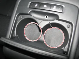
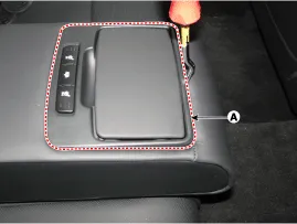
Rear Seat Armrest Switch
| 1. |
Disconnect the negative (-) battery terminal. |
| 2. |
Remove the drink holder pad (A).
|
| 3. |
Loosen the mounting screws (A).
|
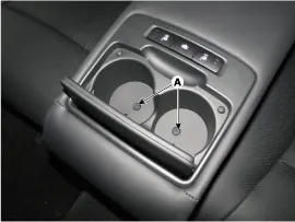
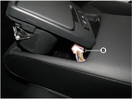
| 4. |
Using a screwdriver or remover, remove the rear seat armrest drink holder assembly (A).
|
| 5. |
Disconnect the connector (B).
|
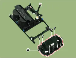
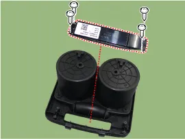
| 6. |
Remove the seat heat switch (A) after loosening the mounting screws.
|
| Inspection |
| 1. |
Power seat switch sends/receives signals via CAN
communication so it is impossible to check the electric current of
switch components. |
| 2. |
Inspect the seat heater system using GDS.
Circuit Diagram Component Location 1. Heating ventilation blower2. Heating ventilation blower ECU3. Thermoelectric element [TED] Other information:Hyundai Genesis (DH) 2013-2016 Service Manual: Head Up Display Unit Repair proceduresRemoval 1. Disconnect the negative (-) battery terminal. 2. Remove the head up display bezel (A). 3. Remove the instrument cluster. (Refer to Indicators And Guages - "Instrument Cluster") 4. Remove the head up display unit bracket (A) after loosening the mounting nuts. Hyundai Genesis (DH) 2013-2016 Service Manual: Compressor Description and OperationDescription The compressor is the power unit of the A/C system. It is located on the side of engine block and driven by a V-belt of the engine. The compressor changes low-pressure and low-temperature refrigerant gas into high-pressure and high-temperature refrigerant gas. Categories

Copyright © 2026 www.hgenesisdh.com - 0.0234
|
