Hyundai Genesis (DH): Evaporative Emission Control System / Schematic Diagrams
Hyundai Genesis (DH) 2013-2016 Service Manual / Emission Control System / Evaporative Emission Control System / Schematic Diagrams
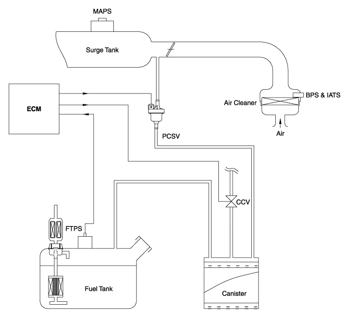
| Schematic Diagram |
| |
Inspection [System Inspection] 1. Disconnect the vapor hose from the throttle body and connect a vacuum pump to the nipple on the throttle body. 2.
Other information:
Hyundai Genesis (DH) 2013-2016 Service Manual: Components and Components Location
S
Hyundai Genesis (DH) 2013-2016 Service Manual: Troubleshooting
Troubleshooting Problem Symptoms Table Before replacing or repairing air conditioning components, first determine if the malfunction is due to the refrigerant charge, air flow or compressor. Use the table below to help you find the cause of the problem.
Categories
- Manuals Home
- Hyundai Genesis Owners Manual
- Hyundai Genesis Service Manual
- 4 Wheel Drive (AWD) System
- Starter Repair procedures
- Parking Assist Sensor Repair procedures
- New on site
- Most important about car

Copyright © 2026 www.hgenesisdh.com - 0.0204