Hyundai Genesis (DH): Horn / Repair procedures
| Removal |
| 1. |
Remove the front bumper cover.
(Refer to Body - "Front Bumper Cover") |
| 2. |
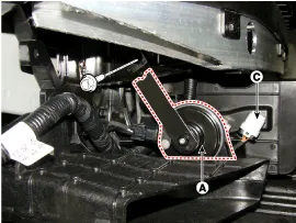
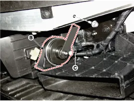
After loosening each mounting bolt of the low-pitch horn (A)
and high-pitch horn (B), detach the connector (C) and remove the horn.
|
| Installation |
| 1. |
After connecting the horn connectors, install both high-pitch and low-pitch horns. |
| 2. |
Install the front bumper cover. |
| Inspection |
| 1. |
The relay on the horn of this vehicle is implanted into the metal core block PCB of the engine room relay block. |
The semi-conductor type relay inserted in the PCB is
impossible to replace. If the relay needs to be replaced, replace the
metal core box and conduct a test on it. |

Component Location 1. Horn switch2. Horn relay (Built - in Metal Core Block PCB)3. Horn (Low pitch)4. Horn (High pitch)5. Clock spring
Other information:
Hyundai Genesis (DH) 2013-2016 Service Manual: Specifications
S
Hyundai Genesis (DH) 2013-2016 Service Manual: Receiver-Drier Repair procedures
Replacement 1. Remove the condenser. 2. Remove the cap (B) on the bottom of the condenser with the L wrench (A). Tightening torque : 9.81 ~ 14.71 N.m (1.0 ~ 1.5 kgf.m, 7.2 ~ 10.8 lb-ft) 3. Remove the receiver-drier (A) from condenser using a long nose plier.
Categories
- Manuals Home
- Hyundai Genesis Owners Manual
- Hyundai Genesis Service Manual
- Body (Interior and Exterior)
- Body Electrical System
- Parking Assist Sensor Repair procedures
- New on site
- Most important about car

Copyright © 2026 www.hgenesisdh.com - 0.0272