Hyundai Genesis (DH): Fuses And Relays / Relay Box (Engine Compartment) Repair procedures
Hyundai Genesis (DH) 2013-2016 Service Manual / Body Electrical System / Fuses And Relays / Relay Box (Engine Compartment) Repair procedures
| Inspection |
| 1. |
Disconnect the negative (-) battery terminal. |
| 2. |
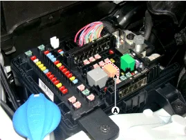
Pull out the relay from the engine compartment relay box. |
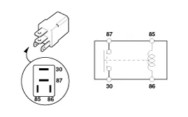
Power Relay (Type A)
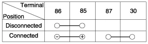
Check for continuity between the terminals.
A : start relay
| 1. |
After supplying power to between No. 85 and 86 power relay
terminals, check that there is continuity between No. 30 and 87
terminals. |
| 2. |
After disconnecting power between No. 85 and 86 power relay
terminals, check that there is no continuity between No. 30 and 87
terminals.
Engine Room Relay Box
Diesel Box
|

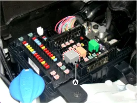
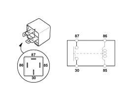
Power Relay (Type B)
Check for continuity between the terminals.
A : Cooling fan relay
| 1. |
After supplying power to between No. 85 and 86 power relay
terminals, check that there is continuity between No. 30 and 87
terminals. |
| 2. |
After disconnecting power between No. 85 and 86 power relay
terminals, check that there is no continuity between No. 30 and 87
terminals.
|
Metal Core PCB block
| 1. |
Disconnect the battery(-) terminals. |
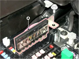
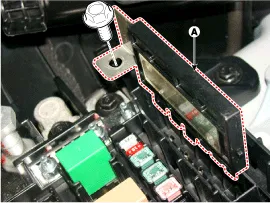
| 2. |
Push the four hooks in the direction of the arrow and lift up the metal core PCB block (A).
|

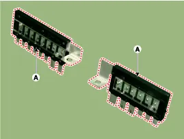
| 3. |
Remove the metal core PCB by disconnecting the connector. |
Fuse
| 1. |
Check that the fuse holders are loosely held and that the fuses are securely fixed by the holders. |
| 2. |
Check that each fuse circuit has the exact fuse capacity. |
| 3. |
Check the fuses for any damage.
|

Multi Fuse
Engine room fuse is to optimize the package.
|

Component Location Engine room junction block Battery junction block
Component Location Interior Junction Block
Other information:
Hyundai Genesis (DH) 2013-2016 Service Manual: Parking Assist Sensor Repair procedures
Removal 1. Disconnect the negative (-) battery terminal. 2. Remove the front/rear bumper cover. (Refer to Body - "Front Bumper Cover") (Refer to Body - "Rear Bumper Cover") 3. Disconnect the connector (B) from the parking assist sensor (A).
Hyundai Genesis (DH) 2013-2016 Service Manual: Blower Unit Components and Components Location
Component Location Components 1. Seal2. Intake Duct Case3. Intake Door4. Intake Actuator5. Intake Duct Case (A)6. Climate Control Air Filter7. Climate Control Air Filter Cover8. Cluster Ionizer9. Blower Upper Case10. Blower Lower Case11. Power Mosfet12.
Categories
- Manuals Home
- Hyundai Genesis Owners Manual
- Hyundai Genesis Service Manual
- Starter Repair procedures
- Emission Control System
- Front Door
- New on site
- Most important about car

Copyright © 2026 www.hgenesisdh.com - 0.03