
Hyundai Genesis (DH): Rear Suspension System / Rear Stabilizer Bar Repair procedures
Hyundai Genesis (DH) 2013-2016 Service Manual / Suspension System / Rear Suspension System / Rear Stabilizer Bar Repair procedures
| Removal |
| 1. |
Loosen the wheel nuts slightly. Raise the vehicle, and make sure it is securely supported. |
| 2. |
Remove the front wheel and tire (A) from the rear hub.
|


| 3. |
Loosen the bolts and remove the cover (A). [TAU]
|

| 4. |
Using a hex wrench, loosen the nut (A) while fixing the end of stabilizer link and then disconnect the link from the lower arm.
|

| 5. |
Loosen the mounting bolt (A) and then remove the stabilizer bar (B).
|

| 6. |
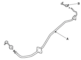
Disconnect the rear stabilizer link (B) with the stabilizer bar (A).
|
| 7. |
Installation in the reverse order of removal. |
| Inspection |
| 1. |
Check the bushing for wear and deterioration. |
| 2. |
Check all the bolts. |
| 3. |
Check the stabilizer bar for deformation. |
Removal 1. Loosen the wheel nuts slightly. Raise the vehicle, and make sure it is securely supported. 2. Remove the front wheel and tire (A) from the rear hub.
Other information:
Hyundai Genesis (DH) 2013-2016 Service Manual: Parking Assist Sensor Repair procedures
Removal 1. Disconnect the negative (-) battery terminal. 2. Remove the front/rear bumper cover. (Refer to Body - "Front Bumper Cover") (Refer to Body - "Rear Bumper Cover") 3. Disconnect the connector (B) from the parking assist sensor (A).
Hyundai Genesis (DH) 2013-2016 Service Manual: A/C Pressure Transducer Description and Operation
Description The A/C Pressure Transducer (APT) converts the pressure value of high-pressure line into voltage value after measuring it. By converted voltage value, engine ECU controls the cooling fan by operating it at high speed or low speed.
Categories
- Manuals Home
- Hyundai Genesis Owners Manual
- Hyundai Genesis Service Manual
- Parking Assist Sensor Repair procedures
- Suspension System
- Restraint
- New on site
- Most important about car

Copyright В© 2026 www.hgenesisdh.com - 0.0292