Hyundai Genesis (DH): Power Door Mirrors / Power Door Mirror Switch Components and Components Location
Hyundai Genesis (DH) 2013-2016 Service Manual / Body Electrical System / Power Door Mirrors / Power Door Mirror Switch Components and Components Location
| Components |
Component Location 1. Power door mirror2. Power door mirror switch3. Power folding mirror switch
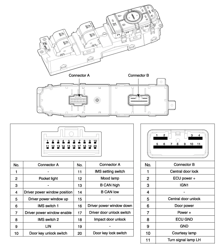
Circuit Diagram
Other information:
Hyundai Genesis (DH) 2013-2016 Service Manual: Rheostat Repair procedures
Inspection 1. Disconnect the negative (-) battery terminal. 2. Remove the crash pad lower panel. (Refer to Body - "Crash Pad Lower Panel") 3. Remove the lower crash pad switch assembly (A) after disengaging the mounting clip. 4. Remove the rheostat switch connector (A).
Hyundai Genesis (DH) 2013-2016 Service Manual: Components and Components Location
C
Categories
- Manuals Home
- Hyundai Genesis Owners Manual
- Hyundai Genesis Service Manual
- Body (Interior and Exterior)
- Starter Repair procedures
- Description and Operation
- New on site
- Most important about car

Copyright © 2026 www.hgenesisdh.com - 0.021