Hyundai Genesis (DH): Parking Guide System (PGS) / PGS Unit (Back & Blinde Unit) Repair procedures
| Removal |
| 1. |
Disconnect the negative (-) battery terminal. |
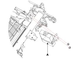
| 2. |
Remove the glove box housing (A).
(Refer to Body - "Glove Box") |
| 3. |
Remove the PGS unit (A) after loosening the nuts.
|
| Installation |
| 1. |
Install the PGS unit. |
| 2. |
Install the glove box housing. |
| 3. |
Connector the negative (-) battery terminal. |
Circuit Diagram Input / Output Terminal Voltage No.SignalDescriptionlevel1ACCACCOFF(Less than 1V), ON(More than 8V)4C-CAN-LHigh Speed CAN low-11V-OUTVideo Out-13IGNIGN SignalON(More than 9V) / OFF(Less than 1V)16C-CAN-HHigh Speed CAN high-18GND-RRear Camera GND-19REAR-POWERVCC-REARON(6~7V) / OFF(Less than 1V)20V-IN-RRear Video Input-20VGND-RRear Video Gnd-22SERIAL LINETop View Control-24VGNDVideo Out GND-
Other information:
Hyundai Genesis (DH) 2013-2016 Service Manual: Receiver-Drier Repair procedures
Replacement 1. Remove the condenser. 2. Remove the cap (B) on the bottom of the condenser with the L wrench (A). Tightening torque : 9.81 ~ 14.71 N.m (1.0 ~ 1.5 kgf.m, 7.2 ~ 10.8 lb-ft) 3. Remove the receiver-drier (A) from condenser using a long nose plier.
Hyundai Genesis (DH) 2013-2016 Service Manual: Cluster Ionizer Repair procedures
Inspection 1. Press the MODE switch more than 4 times within 2 seconds while pressing the OFF switch. DisplayFail description00Normal51Cluster ion generator fault * For diagnostic procedure, refer to DTC guide. Replacement 1. Disconnect the negative (-) battery terminal.
Categories
- Manuals Home
- Hyundai Genesis Owners Manual
- Hyundai Genesis Service Manual
- Repair procedures
- Body (Interior and Exterior)
- General Information
- New on site
- Most important about car
