Hyundai Genesis (DH): Engine Control System / Manifold Absolute Pressure Sensor (MAPS) Schematic Diagrams
Hyundai Genesis (DH) 2013-2016 Service Manual / Engine Control / Fuel System / Engine Control System / Manifold Absolute Pressure Sensor (MAPS) Schematic Diagrams
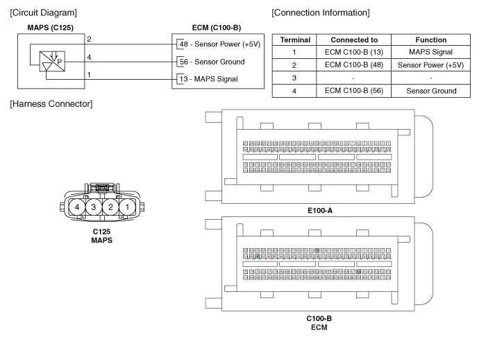
| Circuit Diagram |
Signal Waveform
Inspection 1. Connect the GDS on the Data Link Connector (DLC). 2. Measure the output voltage of the MAPS at idle and with ignition ON. ConditionOutput Voltage (V)IG ONApprox.
Other information:
Hyundai Genesis (DH) 2013-2016 Service Manual: Front Fog Lamps Repair procedures
Removal 1. Disconnect the negative (-) battery terminal. 2. Remove the front bumper. (Refer to Body - "Front Bumper Cover") 3. Disconnect the front fog lamp connector (A). 4. Remove the front fog lamp assembly (A) after loosening the mounting nut.
Hyundai Genesis (DH) 2013-2016 Service Manual: Auto Light Sensor Components and Components Location
C
Categories
- Manuals Home
- Hyundai Genesis Owners Manual
- Hyundai Genesis Service Manual
- Description and Operation
- Description and Operation
- Engine Mechanical System
- New on site
- Most important about car

Copyright © 2026 www.hgenesisdh.com - 0.032