Hyundai Genesis (DH): Automatic Transmission Control System / Inhibitor Switch Description and Operation
Hyundai Genesis (DH) 2013-2016 Service Manual / Automatic Transmission System (SBC) / Automatic Transmission Control System / Inhibitor Switch Description and Operation
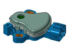
| Description |
Inhibitor Switch monitors the lever's position(PRND) and is used to control gear setting signals.
Inspection 1. Turn ignition switch OFF. 2. Disconnect the E Module connector. 3. Measure resistance between solenoid valve terminals. 4.
Specifications ? Type: Combination of output signals from 4 terminals Power supply (V)12Output typeCombination of output signals Signal Code Table PIN No.
Categories
- Manuals Home
- Hyundai Genesis Owners Manual
- Hyundai Genesis Service Manual
- Suspension System
- Engine Mechanical System
- Active Air Flap(AAF) Repair procedures
- New on site
- Most important about car

Copyright © 2026 www.hgenesisdh.com - 0.0282